
2. PWM output
In the previous chapters, we wrote Python applications for operating GPIO peripherals through the Python libraries python3-libgpiod and python-periphery. Finally, on the Lubancat board, the LED light on the board and the button resources are used through the Python application program. Then in this section, we will then introduce another function provided by the above library, PWM waveform output.
In this experiment, GPIO pins will be used to control LED lights for PWM output. At that time, you can view the experimental phenomenon through the light and dark changes of the LED light (the board may need an external LED).
2.1. PWM experiment
By controlling the high and low level changes introduced by GPIO, we can do some simple controls, such as controlling the on and off of LED lights. If we further adjust the frequency and duration of GPIO pin level changes, then based on this, the control we can do can become more complicated, which is PWM (Pulse Width Modulation).
Usually we can use PWM waveform output to achieve many functions, such as controlling the brightness of LED lights, the loudness of passive buzzers, and even controlling small servos. In this section of the experiment, we control the LED lights to achieve the effect of LED breathing lights by outputting PWM (take the LubanCat 2 board as an example, with external LEDs).
Regarding how PWM works, we will not do too much research here, and you can search for the principle of PWM by yourself. The focus of this section is to provide examples of PWM output, of course, this is inseparable from the Python library we introduced earlier.
重要
If there is no special mention, the tutorials in this book are based on the Python 3.8.10 version (extboot partition Ubuntu20.04 image) for experiments and explanations.
2.2. Experiment preparation
Some GPIOs on the board may be occupied by the system, you can comment out the loading of some device tree nodes or device tree plug-ins, restart the system, and release the corresponding GPIO pins. Of course, you can also change the pin test. The pins of LubanCat_RK series boards are as follows: “LubanCat-RK Series-40pin Pin Mapping”
If Permission denied or similar words appear, please pay attention to user permissions. Most of the functions of operating hardware peripherals almost require root user permissions.
The simple solution is to add sudo or run the program as root before executing the statement.
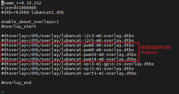
How to enable the pwm device tree plugin (take LubanCat 2 as an example):
# The configuration files of different boards are different from pwm, taking LubanCat 2 as an example, the configuration file is uEnvLubanCat 2.txt,
# Can turn on pwm8, pwm9, pwm10, pwm14
# Log in to the system terminal and open the '/boot/uEnv/uEnvLubanCat 2.txt' file

sudo vim /boot/uEnv/uEnvLubanCat 2.txt
#Enter edit mode, cancel the comment in front of pwm, save and exit the file, restart the system.
# Enter the following command in the terminal to view the PWM resources of the current board:
ls /sys/class/pwm/
The PWM resource example on the board is for reference only:
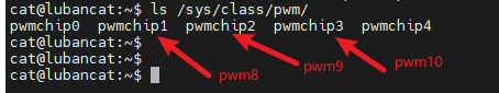
pwmchip0 is pwm4, which is used for backlight adjustment. The pwmchip1 in the back of the picture is added when we open the device tree, corresponding to pwm8 on the hardware, and so on.
2.3. Use python-periphery
The PWM output supported by the python-periphery library is implemented based on the PWM subsystem of Linux, so if you want to use this library for PWM output, you need the board to provide support. Like the Lubancat board, you can perfectly use the python-periphery library to achieve PWM output. In this way, we don’t need to use GPIO to simulate PWM output at the software level.
For the content related to the PWM subsystem, refer to “PWM Control” 。
2.3.1. Install python-periphery
重要
Be sure to skip this if you installed the library in the previous section.
python-periphery is installed as follows:
# Use the following command to install on the board
sudo pip3 install python-periphery
2.3.2. peripheral output PWM
The sample code for PWM output using python-periphery library is as follows:
1 2 3 4 5 6 7 8 9 10 11 12 13 14 15 16 17 18 19 20 21 22 23 24 25 26 27 28 29 30 31 32 33 34 35 | from periphery import PWM
import time
try:
# Define the duty cycle increment step size
step = 0.05
# Define the maximum range of range
rangeMax = int(1/0.05)
# Turn on PWM 8, channel 0, which corresponds to the PWM8 peripheral on the development board
pwm = PWM(1, 0)
# Set the PWM output frequency to 1 kHz
pwm.frequency = 1e3
# Set the duty cycle to 0%, the ratio of the high level time in one cycle to the entire cycle time
pwm.duty_cycle = 0.00
# Turn on the PWM output
pwm.enable()
while True:
for i in range(0,rangeMax):
# sleep step seconds
time.sleep(step)
# Set the duty cycle to add step% each time, use round to avoid floating-point calculation errors
pwm.duty_cycle = round(pwm.duty_cycle+step,2)
# Always off for 1 second
if pwm.duty_cycle == 0.0:
time.sleep(1)
for i in range(0,rangeMax):
time.sleep(step)
pwm.duty_cycle = round(pwm.duty_cycle-step,2)
except:
print("Some errors occur!\n")
finally:
# Turn off the LED on exit
pwm.duty_cycle = 0.0
# Release resources
pwm.close()
|
Code description:
Line 10, a PWM object is created
Lines 12 and 14 initialize the parameters of the PWM object respectively, which are the frequency and duty cycle of the PWM output waveform
Line 16, enable PWM waveform output according to the corresponding parameters
提示
If you are not familiar with the use of some python modules of PWM, you can enter the python terminal interactive mode and use the commands from periphery import PWM and help(PWM) to view the help about PWM modules.
2.3.2.1. Experimental operation
The sample code uses the LubanCat 2 board, and the operation is as follows:
# Confirm that the python-periphery package is installed
# Enable the PWM device tree plug-in, confirm the enabled pwm

# Execute the following command in the directory where the board pwm_test.py is located
sudo python3 pwm_test.py
If you are prompted about permission issues, you can switch to the root user and run:
#Switch to root, is the password root
su root
If you connect an external LED, you can see that the onboard LED lights will change in brightness, or you can view the waveform through an oscilloscope.