
5. SPI communication
In the previous chapters, we talked about the use of the I2C communication protocol.
In this chapter, we then introduce the use of another communication protocol, the SPI communication protocol.
The SPI communication protocol is also a common communication protocol in electronic device communication.
However, the communication rate of the SPI communication protocol is higher, and it uses a full-duplex communication method.
Therefore, we can often find the interface specified under the SPI communication protocol on electronic devices that require communication speed.
For example, some small size LCD screen, AD conversion chip, nRF series radio frequency module, SPI-FLASH and so on.
Regarding the specific content of the SPI protocol, we will not explore too much here, and you can search for the relevant knowledge of the SPI communication protocol to learn.
In this chapter, our focus is to use the python-periphery library introduced earlier to use the SPI master on our Lubancat board.
5.1. SPI experiment
Since the SPI communication protocol supports full-duplex communication, we can conduct experimental verification through loopback testing. In the experiment, we just connect the MOSI and MISO interfaces of the SPI interface together.
5.2. Experiment preparation
5.2.1. Add SPI resource
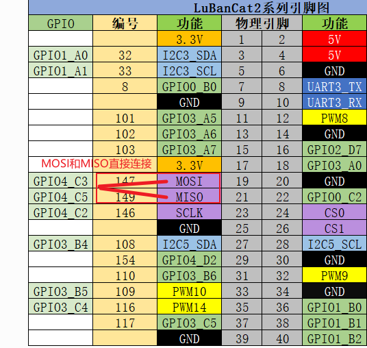
The GPIO on the board may not be multiplexed as I2C, which can be loaded by setting the device tree plug-in. The pin reference of the LubanCat_RK series board is as follows: “LubanCat-RK Series-40pin Pin Mapping”
Let’s take LubanCat 2 as an example to open the SPI device tree plug-in (the pins derived from LubanCat 2 can use spi3):
# The configuration files of different boards are different from i2c, taking LubanCat 2 as an example, the configuration file is uEnvLubanCat 2.txt
# Log in to the system terminal and open the /boot/uEnv/uEnvLubanCat 2.txt file

sudo vim /boot/uEnv/uEnvLubanCat 2.txt
#Enter edit mode, cancel the comment in front of I2c3, save and exit the file, restart the system
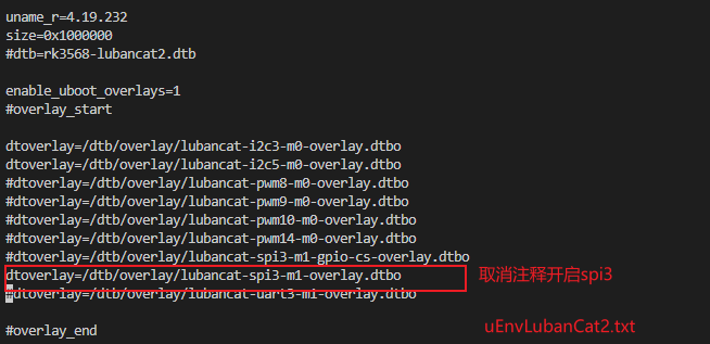
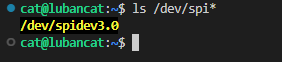
After restarting, check whether the SPI resource of the board is loaded:
# Enter the following command in the terminal to view the SPI resource:
ls -l /dev/spi*
The I2C resource example on the board is for reference only:
For the SPI test on linux, you can refer to “SPI Communication”
5.2.2. Hardware connection
Note: In the hardware connection section, you need to make reference adjustments to the content of this chapter according to your own development environment and other conditions.
Perform a loopback test, the connection is as follows (LubanCat 2):
5.3. Use python-periphery
The SPI function supported by the python-periphery library is implemented based on the Linux SPI system, so if you want to use the library to use the SPI function, you need the board to provide support. Like the Lubancat board, you can perfectly use the SPI communication function of the python-periphery library. In this way, we don’t need to use GPIO to simulate the SPI master function at the software level.
5.3.1. Install python-periphery
重要
Be sure to skip this if you installed the library in the previous section.
python-periphery is installed as follows:
# Use the following command to install on the board
sudo pip3 install python-periphery
5.3.2. The periphery uses the SPI function
The sample code for SPI function using python-periphery library is as follows:
1 2 3 4 5 6 7 8 9 10 11 12 13 14 15 16 17 18 19 | """ periphery spi test """
from periphery import SPI
# List of data to be sent
data_out = [0xAA, 0xBB, 0xCC, 0xDD]
try:
# Apply for SPI resources, turn on the spidev3.0 controller, configure the SPI master to work in mode 0, and work at 1MHz
spi = SPI("/dev/spidev3.0", 0, 1000000)
# Send data and receive data to the data_in list at the same time
data_in = spi.transfer(data_out)
# Print the sent data content
print("Data sent: [0x{:02x}, 0x{:02x}, 0x{:02x}, 0x{:02x}]".format(*data_out))
print("Received data: [0x{:02x}, 0x{:02x}, 0x{:02x}, 0x{:02x}]".format(*data_in))
finally:
# Close the requested SPI resource
spi.close()
|
Code description:
Line 5, apply for SPI resources, occupy the SPI3 host, and configure the corresponding working mode
Line 9, constructing a list of messages to be sent
Line 12, start SPI transmission, because SPI is a full-duplex communication mode, and it can also receive data while sending data
Line 19, release SPI resource, release SPI3 master
5.3.2.1. Experimental operation
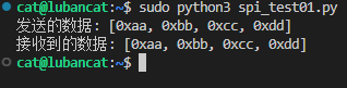
The sample code uses the LubanCat 2 board, and the operation is as follows:
# Execute the following command in the directory where the board spi_test.py is located
sudo python3 spi_test.py

# It can be seen that the received data printed by the terminal is consistent with the sent data
Since the MOSI and MISO interfaces of the SPI interface have been connected during the hardware connection. So when the SPI controller sends out data, it will also receive the data back, which is the loopback test.
5.4. Method 2: Using Adafruit Blinka
Adafruit Blinka is similar to python-periphery, and the SPI communication is also implemented based on the SPI subsystem of Linux. It’s just that there is a big difference in the usage of the code.
5.4.1. Installing Adafruit Blinka
重要
Be sure to skip this if you installed the library in the previous section.
Adafruit Blinka is installed as follows:
# Use the following command to install on the board
sudo apt -y install python3-libgpiod python-periphery # 注:如已安装,忽略此步
sudo pip3 install Adafruit-Blinka
5.4.2. Adafruit - Blinka using SPI master
The sample code for input and output using this Adafruit Blinka is as follows:
1 2 3 4 5 6 7 8 9 10 11 12 13 14 15 16 17 18 19 20 21 22 23 24 25 26 27 28 29 30 31 32 33 34 35 36 37 38 39 40 41 42 43 | """ blinka spi test """
import busio
from board import *
# Data sending and receiving buffer
OutBuffer = [0xAA, 0xBB, 0xCC, 0xDD]
InBuffer = bytearray(4)
try:
# Apply for spi resources
spi = busio.SPI(SCLK, MOSI, MISO)
# Lock the SPI first when configuring
spi.try_lock()
# Configure the SPI host operating rate as 1MHz, clock polarity as 0, clock phase as 0, and a single data bit as 8 bits
spi.configure(1000000, 0, 0, 8)
# The configuration operation is completed and unlocked
spi.unlock()
# SPI communication, while sending and reading, the sent data is stored in OutBuffer, and the read data is stored in InBuffer
spi.write_readinto(OutBuffer, InBuffer)
print(
"(write_readinto)Received data: [0x{:02x}, 0x{:02x}, 0x{:02x}, 0x{:02x}]".format(
*InBuffer
)
)
# SPI communication, write-only usage demonstration
spi.write(OutBuffer)
print(
"(OutBuffer)Sent data: [0x{:02x}, 0x{:02x}, 0x{:02x}, 0x{:02x}]".format(*OutBuffer)
)
InBuffer = [0, 0, 0, 0]
# SPI communication, read-only usage demonstration
spi.readinto(InBuffer)
print(
"(readinto)Received data: [0x{:02x}, 0x{:02x}, 0x{:02x}, 0x{:02x}]".format(*InBuffer)
)
finally:
# Release spi resources
spi.deinit()
|
Code description:
Line 11: Apply for SPI resources, occupying SPI3 host
Lines 14~18: Configure the working mode of the SPI3 host, and the resources need to be locked before configuration
Line 21: Use the SPI3 host to send the data in the byte array OutBuffer, and read the data to the InBuffer at the same time
Line 30: Use SPI3 to send data only, not to read
Line 37: Use SPI3 to read data only, not send
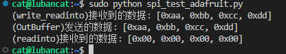
After running it shows:
In addition, there is a supporting routine io/spi/ssd1306_spi_status.py, which will use spi to control the screen display. For details, refer to the previous subsection of i2c using the Adafruit_CircuitPython_SSD1306 library to control the screen display.
Adafruit Blinka The library does not provide examples of using SPI objects. You can refer to related API functions: CircuitPython SPI.