
1. Control GPIOs
重要
If there is no special mention, the tutorials in this book are based on the Python 3.8.10 version (extboot partition Ubuntu20.04 image) for experiments and explanations.
There is no difference between developing pure software Python applications on Lubancat boards and PCs. The following chapters focus on how to use Python to control peripheral interfaces such as GPIO, PWM, ADC, I2C, and SPI that are rarely used in pure PC programming.
When controlling these peripheral interfaces, the following Python packages are mainly used:
python3-libgpiod: The python version of the standard GPIO libgpiod library, which only supports controlling IO input and output.
python-periphery: Support basic control of GPIO, PWM, I2C, SPI, UART and other interfaces.
Adafruit Blinka: It supports GPIO, PWM, I2C, SPI, UART, etc., and also has some application examples of commonly used sensors and OLED screens.
They have their own characteristics, you can try them all.
1.1. libgpiod basic concept
GPIO is mainly used to output high and low levels externally. When controlling GPIO, it will basically involve the control of libgpiod. We mainly need to know the naming method of the board pins.
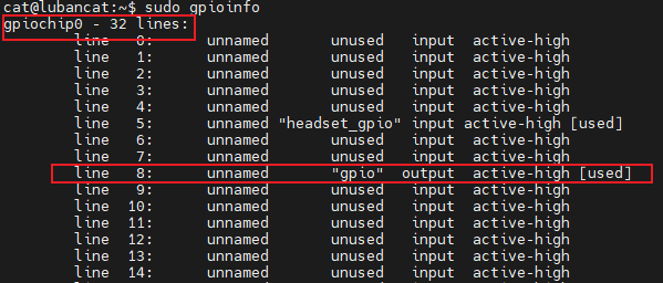
The GPIO pins of the CPU are named using (chip, line), and you can view them using the following command:
# Execute the following command on the board
sudo gpioinfo

# If it prompts that the command cannot be found, use the following method to install
sudo apt -y install gpiod libgpiod-dev

# The following is the output of gpioinfo
gpiochip0 - 32 lines:
    line   0:      unnamed       unused   input  active-high
    line   1:      unnamed       unused   input  active-high
    line   2:      unnamed       unused   input  active-high
    line   3:      unnamed       unused   input  active-high
    line   4:      unnamed       unused   input  active-high
    line   5:      unnamed "headset_gpio" input active-high [used]
# ...

    line  31:      unnamed       unused   input  active-high
gpiochip1 - 32 lines:
        line   0:      unnamed       unused   input  active-high
        line   1:      unnamed       unused   input  active-high
# ...
        line  31:      unnamed       unused   input  active-high
For the correspondence between the pin headers and GPIO (chip, line) drawn from the board, please refer to the specific instructions of the board.
For a more detailed description of libgpiod, please refer to the description on the right: “Controlling IO with libgpiod”
1.2. Experiment preparation
Some GPIOs on the board may be used for other functions, you can comment out the loading of some device tree nodes or device tree plug-ins, restart the system, and release the corresponding GPIO pins. Of course, you can also change the pin test. The pins of LubanCat_RK series boards are as follows: “LubanCat-RK Series-40pin Pin Mapping”
Most of the functions of operating hardware peripherals almost require the root user authority. The simple solution is to add sudo before executing the statement or run the program as the root user.
1.3. Method 1: Use python3-libgpiod
1.3.1. Install python3-libgpiod
The python3-libgpiod package makes it easy to control GPIO pins using Python. Currently python3-libgpiod has no official documentation, you can use help to view the help after importing the package. Its installation and viewing help are as follows:
# Use the following command to install on the board
sudo apt -y install python3-libgpiod

# Enter python exchange mode, test and view help
python3
import gpiod
help(gpiod)

# The following is the help description of the output
NAME
    gpiod - Python bindings for libgpiod.

DESCRIPTION
    This module wraps the native C API of libgpiod in a set of python classes.
# ...
1.3.2. libgpiod output
The sample code for controlling GPIO lighting (output) using this python3-libgpiod package is as follows:
1 2 3 4 5 6 7 8 9 10 11 12 13 14 15 16 17 18 19 20 21 22 | import time
import gpiod
# Modify the Chip and Line used according to the LED light connection of the specific board. If there is no LED, you can connect it externally
LINE_OFFSET = 8
chip0 = gpiod.Chip("0", gpiod.Chip.OPEN_BY_NUMBER)
gpio0_b0 = chip0.get_line(LINE_OFFSET)
gpio0_b0.request(consumer="gpio", type=gpiod.LINE_REQ_DIR_OUT, default_vals=[0])
print(gpio0_b0.consumer())
try:
while True:
gpio0_b0.set_value(1)
time.sleep(0.5)
gpio0_b0.set_value(0)
time.sleep(0.5)
finally:
gpio0_b0.set_value(1)
gpio0_b0.release()
|
Code description:
On line 7, a gpiod.Chip object chip0 with a chip ID of 0 is created
Line 9, set to use line8 of the chip0 object as a pin
Line 10, apply for gpio, set it as output, and output low level by default
The following code directly uses the gpio0_b0 object to control the selected GPIO output high and low levels, so as to control the LED light on and off.
This example and the following content all use the LubanCat 2 board as the experimental object, so (chip, line)=(0, 8) in the code is selected according to the pin definition of the board. If you use other boards, you only need to modify the corresponding number.
1.3.2.1. Experimental operation
The sample code uses the LubanCat 2 board, the source code can refer to the supporting routine, the operation is as follows:
# Confirm that the python3-libgpiod package is installed
# Execute the following command in the directory where the board blink.py is located, and root permission is required
sudo python3 blink.py

# If an LED is connected to this pin, the light will blink
Use another terminal, use the gpioinfo command, you can see that the gpio (0, 8) pin has been applied for use:
1.3.3. libgpiod input and output
Similarly, the sample code for detecting GPIO input (keypress) using this python3-libgpiod package is as follows:
1 2 3 4 5 6 7 8 9 10 11 12 13 14 15 16 17 18 19 20 21 22 23 24 25 26 27 | import gpiod
# Modify the Chip and Line used according to the LED light and button connection of the specific board
# Here take LubanCat 2 as an example, use GPIO0_B0 to connect to LED, and GPIO0_C2 to connect to button
LED_LINE_OFFSET = 8
BUTTON_LINE_OFFSET = 18
chip0_led = gpiod.Chip("0", gpiod.Chip.OPEN_BY_NUMBER)
chip0_button = gpiod.Chip("0", gpiod.Chip.OPEN_BY_NUMBER)
led = chip0_led.get_line(LED_LINE_OFFSET)
led.request(consumer="LED", type=gpiod.LINE_REQ_DIR_OUT, default_vals=[0])
button = chip0_button.get_line(BUTTON_LINE_OFFSET)
button.request(consumer="BUTTON", type=gpiod.LINE_REQ_DIR_IN)
print(led.consumer())
print(button.consumer())
try:
while True:
led.set_value(button.get_value())
finally:
led.set_value(1)
led.release()
button.release()
|
Code description:
Line 12, set the GPIO control direction of the LED to output
Line 15, set the GPIO control direction of the button as input
Line 23, read the input value of the button pin to control the LED
1.4. Method 2: Use python-periphery
1.4.1. Install python-periphery
python-periphery is functionally similar to python3-libgpiod. However, in addition to supporting GPIO input and output control, the periphery also supports bus protocols such as I2C and SPI.
python-periphery is installed as follows:
# Use the following command to install on the board
sudo pip3 install python-periphery
1.4.2. peripheral input and output
The sample code for input and output using this python-periphery is as follows:
1 2 3 4 5 6 7 8 9 10 11 12 13 14 15 16 17 18 19 20 | from periphery import GPIO
# Modify the Chip and Line used according to the LED light and button connection of the specific board
# Here take LubanCat 2 as an example, use GPIO0_B0 to connect to LED, and GPIO0_C2 to connect to button
LED_CHIP = "/dev/gpiochip0"
LED_LINE_OFFSET = 8
BUTTON_CHIP = "/dev/gpiochip0"
BUTTON_LINE_OFFSET = 18
led = GPIO(LED_CHIP, LED_LINE_OFFSET, "out")
button = GPIO(BUTTON_CHIP, BUTTON_LINE_OFFSET, "in")
try:
while True:
led.write(button.read())
finally:
led.write(True)
led.close()
button.close()
|
Code description:
Lines 5 to 9 define the chip and line numbers of LEDs and buttons
Lines 11~12 create the GPIO output and input objects of led and button respectively
Line 16, read the input value of the button pin to control the LED
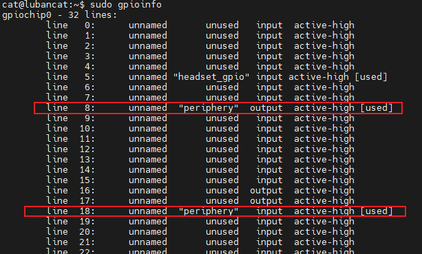
The experimental operation is the same as the previous section. Use another terminal, use the gpioinfo command, you can see that two pins have been applied for use:
1.5. Method 3: Using Adafruit Blinka
1.5.1. Installing Adafruit Blinka
Adafruit Blinka is similar to python-periphery in that it not only supports GPIO input and output control, but also supports I2C, SPI and other bus protocols. But Adafruit also provides richer application demos based on blinka, such as controlling the screen and so on.
Adafruit Blinka is installed as follows:
# Use the following command to install on the board
sudo apt -y install python3-libgpiod # Note: If it has been installed in method 1, ignore this step
sudo pip3 install Adafruit-Blinka
1.5.2. Read before use
The Lubancat RK series boards have been adapted to the Adafruit-Blinka library, but the available resources of the Adafruit-Blinka library on different boards are different.
According to the Lubancat board in your hand, you can modify the resource name used in the corresponding sample program to complete the corresponding experiment.
It should be noted that some boards have limited resources, so the Adafruit-Blinka library function cannot support all boards. If you want to know whether your board supports some functions, you can query the board resource definition. The reference is as follows:
Make sure the Adafruit-Blinka library is installed and the board can be detected before querying.
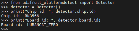
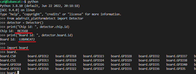
Enter
python3to enter the python3 terminal.Output
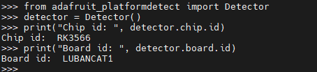
from adafruit_platformdetect import Detectorto add adafruit_platformdetect package;Enter
detector = Detector()followed byprint("Chip id: ", detector.chip.id)andprint("Board id: ", detector.board.id)Detect board and chip id;In the python3 terminal, enter
import boardto import the board package.Enter
board.and double-click the Tab key to display the completion information, which contains the resource content defined by the board.
lubancat-zero series:
LubanCat 1 series:
LubanCat 2 series:
Note that the resources queried here are only the resources we added to adapt the Adafruit-Blinka library. Whether the specific resources can be used depends on the board situation, and you can also try it yourself.
提示
The added board resource is the 40pin lead out, and the setting rule is which pin corresponds to which GPIO. For example, GPIO3 corresponds to the third physical pin of 40pin. If the physical pin is grounded or there is no power supply, for example, there is no GPIO1.
The following formally enters the experimental part.
1.5.3. Adafruit-Blinka input and output
The sample code for using this Adafruit Blinka for input and output is as follows (Here, LubanCat 1 is used as an example, other series need to modify the pins by themselves, etc.):
1 2 3 4 5 6 7 8 9 10 11 12 13 14 15 16 17 18 | import board
import digitalio
# Modify the GPIO used according to the specific board
# Take LubanCat 1 board as an example, board.GPIO11 is the 11th physical pin of 40Ppin, board.GPIO11 = GPIO3_A5 = Pin 101
led = digitalio.DigitalInOut(board.GPIO11)
led.direction = digitalio.Direction.OUTPUT
try:
while True:
led.value=1
time.sleep(0.5)
led.value=0
time.sleep(0.5)
finally:
led.value = True
led.deinit()
|
Code description:
Lines 1~2, board and digitalio are libraries provided by the Blinka package.
Lines 6~7 define the pin board.GPIO11 used and set it as the output direction.
Lines 9-14 make the pin output high and low levels.
The board.GPIO11 pin in the code is the LubanCat 1 pin defined in the Blinka library, use the command:
sudo python digital_io.py
If an LED light is connected to the corresponding pin, you can see the LED flashing.
When we apply for the corresponding board resource, it will detect the board model, and then load the corresponding resource definition according to the board information. So we can directly use the defined resource name, which is more intuitive to use than python-periphery.
More detailed pin definitions can be viewed directly in Source code for Adafruit Blinka :