4. I2C communication
The I2C (IIC) protocol is a commonly used communication protocol in electronic devices, through which we can control various electronic devices (Note: generally controlled devices are slaves).
For example, the common attitude sensor MPU6050, temperature image sensor MLX90640, 0.96-inch OLED display SSD1306, etc., all communicate with the board through the I2C communication protocol (note: generally initiate control for the host) to communicate.
Regarding the specific content of the I2C protocol, we will not explore too much here, and you can search for the relevant knowledge of the I2C communication protocol to learn.
In this chapter, our focus is to use the two Python libraries introduced earlier python-periphery and Adafruit Blinka to use the I2C host on our Lubancat board.
4.1. I2C experiment
In general, we need a specific communication object to complete the experiment in this section, that is, the various types of electronic devices mentioned above.
Considering that the modules or I2C devices in everyone’s hands are different, the introduction to the use of the above Python library is divided into two parts.
One part is the introduction of the official demo of the library, and the other part is the introduction of using the corresponding API in the library and using it in the actual module.
The author is using 0.96-inch OLED display module SSD1306 Embedfire [OLED screen_I2C_0.96 inch] Write examples of using the above-mentioned libraries.
In actual use, the type of devices that the I2C master on the Lubancat board can communicate with is not limited.
Therefore, the author will make detailed comments on the relevant codes in the code. If you do not have the same modules in your hands, you can also perform similar operations to write experimental codes for different modules.
4.2. Experiment preparation
4.2.1. Add I2C resources to the board
The GPIO on the board may not be multiplexed as I2C, which can be loaded by setting the device tree plugin. The pin reference of LubanCat_RK series boards is as follows: “LubanCat-RK Series-40pin Pin Mapping”
Let’s take LubanCat 2 as an example to open the i2c device tree plug-in (LubanCat 2 has two i2c pins):
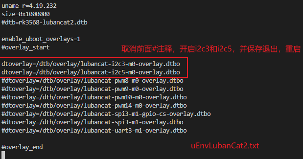
# The configuration files of different boards are different from i2c. Taking LubanCat 2 as an example, the configuration file is uEnvLubanCat 2.txt
# I2c3, i2c5 can be turned on
# Log in to the system terminal and open the /boot/uEnv/uEnvLubanCat 2.txt file

sudo vim /boot/uEnv/uEnvLubanCat 2.txt
#Enter edit mode, cancel the comment in front of I2c3, save and exit the file, restart the system
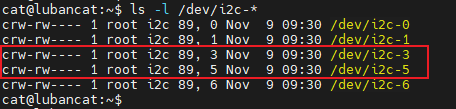
After restarting, check whether the I2C resource of the board is loaded:
# Enter the following command in the terminal to view the I2C resources:
ls -l /dev/i2c-*
The I2C resource example on the board is for reference only:
For some simple i2c-related tests, please refer to “I2C Communication”
4.2.2. Hardware connection
Lubancat LubanCat 2 board, there is no I2C device on the board, and relevant experimental phenomena can be displayed.
Therefore, the experimental phenomenon in this section is shown for you by connecting the peripheral device 0.96-inch OLED display SSD1306 at the hardware level, using I2c3.
The connection is shown in the figure, for reference only (I2c3 of LubanCat 2). The 40pin pin connection table of the oled screen and the board is as follows:
OLED screen pins |
corresponding GPIO |
LubanCat 2 board pins |
|---|---|---|
SDA |
GPIO1_A0 |
I2C3_SDA |
SCL |
GPIO1_A1 |
I2C3_SCL |
GND |
GND |
|
VCC |
3.3V |
4.3. Use python-periphery
The I2C function supported by the python-periphery library is implemented based on the Linux I2C system, so if you want to use the library to use the I2C function, you need the board to provide support. Like the Lubancat board, you can perfectly use the I2C communication function of the python-periphery library. In this way, we don’t need to use GPIO to simulate the I2C host function at the software level.
4.3.1. Install python-periphery
重要
Be sure to skip this if you installed the library in the previous section.
python-periphery is installed as follows:
# Use the following command to install on the board
sudo pip3 install python-periphery
4.3.2. The periphery uses the I2C function
First refer to the sample code for learning the python-periphery library for I2C function use:
1 2 3 4 5 6 7 8 9 10 11 12 13 | from periphery import I2C
# Open i2c1 master
i2c = I2C("/dev/i2c-1")
# Take the EEPROM device as an example, read data from the EEPROM memory address 0x100, and the I2C device address of the EEPROM device is 0x50
msgs = [I2C.Message([0x01, 0x00]), I2C.Message([0x00], read=True)]
# Enable I2C transmission
i2c.transfer(0x50, msgs)
# Print received message
print("0x100: 0x{:02x}".format(msgs[1].data[0]))
# When the operation is complete, shut down the I2C master to free up resources
i2c.close()
|
Code description:
Line 4: Apply for I2C resources and occupy the I2C1 host.
Line 7: Construct the message structure I2C.Message. The first member of I2C.Message is the list of sent data. The second one specifies the function of this message. The default is I2C write command. In the case of write command, the data in the data list will be sent out. If
read=Trueis specified, this message corresponds to an I2C read command, and the read data will be stored in the data member.Line 9, start I2C transmission, send the address of the I2C slave device and the structured message structure.
Line 17, release I2C resources, release I2C1 master.
Through the code examples of EEPROM device operation given in the python-periphery library, we can grasp the basic method of using the library for the I2C master. Then you can start programming and use it for specific devices.
Here the author uses the 0.96-inch OLED display SSD1306 module programming display described above:
1 2 3 4 5 6 7 8 9 10 11 12 13 14 15 16 17 18 19 20 21 22 23 24 25 26 27 28 29 30 31 32 33 34 35 36 37 38 39 40 41 42 43 44 45 46 47 48 49 50 51 52 53 54 55 56 57 58 59 60 61 62 63 64 65 66 67 68 69 70 71 72 73 74 75 76 77 78 79 80 81 82 83 84 85 86 87 88 89 90 91 92 93 94 95 96 97 98 99 100 101 102 | """ Periphery i2c test using 0.96 inch OLED module """
import time
from periphery import I2C
# Turn on the i2c-3 controller
i2c = I2C("/dev/i2c-3")
# Device slave address 0x3c, which is OLED module address
I2CSLAVEADDR = 0x3C
# Read function test using peripheral i2c library
def i2c_read_reg(devregaddr):
"""
Read function test using peripheral i2c library
"""
# Construct data structure
# The first Message is the address of the device to be read
# The second Message is used to store the read back message, pay attention to the added read=True
msgs = [I2C.Message([devregaddr]), I2C.Message([0x00], read=True)]
# Send message, send to i2cSlaveAddr
i2c.transfer(I2CSLAVEADDR, msgs)
print("read the register 0x{:02x} from: 0x{:02x}".format(devregaddr, msgs[1].data[0]))
def oled_write_cmd(cmd):
"""
Use the peripheral i2c library to send functional tests
"""
msgs = [I2C.Message([0x00, cmd])]
i2c.transfer(I2CSLAVEADDR, msgs)
def oled_write_data(data):
"""
Use the peripheral i2c library to send functional tests
"""
msgs = [I2C.Message([0x40, data])]
i2c.transfer(I2CSLAVEADDR, msgs)
def oled_init():
"""
Use OLED module for code function test 0.96 inch OLED module initialization
"""
time.sleep(1)
oled_write_cmd(0xAE)
oled_write_cmd(0x20)
oled_write_cmd(0x10)
oled_write_cmd(0xB0)
oled_write_cmd(0xC8)
oled_write_cmd(0x00)
oled_write_cmd(0x10)
oled_write_cmd(0x40)
oled_write_cmd(0x81)
oled_write_cmd(0xFF)
oled_write_cmd(0xA1)
oled_write_cmd(0xA6)
oled_write_cmd(0xA8)
oled_write_cmd(0x3F)
oled_write_cmd(0xA4)
oled_write_cmd(0xD3)
oled_write_cmd(0x00)
oled_write_cmd(0xD5)
oled_write_cmd(0xF0)
oled_write_cmd(0xD9)
oled_write_cmd(0x22)
oled_write_cmd(0xDA)
oled_write_cmd(0x12)
oled_write_cmd(0xDB)
oled_write_cmd(0x20)
oled_write_cmd(0x8D)
oled_write_cmd(0x14)
oled_write_cmd(0xAF)
def oled_fill(filldata):
"""
Clear the OLED screen
"""
for i in range(8):
oled_write_cmd(0xB0 + i)
# page0-page1
oled_write_cmd(0x00)
# low column start address
oled_write_cmd(0x10)
# high column start address
for j in range(128):
oled_write_data(filldata)
# Code testing
try:
# Initialize the OLED screen, SSD1306 is necessary
oled_init()
# Clear the OLED screen
oled_fill(0xFF)
# Read register test
i2c_read_reg(0x10)
finally:
print("Test ended normally")
# Release resources
i2c.close()
|
It is not the focus of this tutorial on what commands to send through the I2C host to control the 0.96-inch OLED display SSD1306 module.
The purpose of the tutorial is to provide you with a reference object for the use of the API functions of the relevant library through the provided sample code.
4.3.2.1. Experimental operation
The sample code uses the LubanCat 2 board, and the operation is as follows:
# Execute the following command in the directory where the board i2c_test.py is located
sudo python3 i2c_test_periphery.py
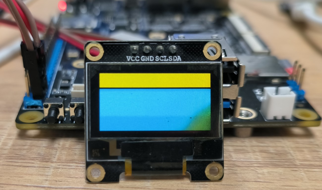
# It can be seen that the connected OLED screen is cleared to display color blocks, and the read register information is printed out in the terminal
Display reference (feel free to take an old screen for testing):
4.4. Method 2: Using Adafruit Blinka
Adafruit Blinka is similar to python-periphery in that the I2C communication is also implemented based on the I2C subsystem of Linux. It’s just that there is a big difference in the usage of the code.
4.4.1. Installing Adafruit Blinka
重要
Be sure to skip this if you installed the library in the previous section.
Adafruit Blinka is installed as follows:
# Use the following command to install on the board
sudo apt -y install python3-libgpiod python-periphery # Note: If already installed, ignore this step
sudo pip3 install Adafruit-Blinka

sudo pip3 install machine
4.4.2. Adafruit - Blinka using I2C master
The sample code for input and output using this Adafruit Blinka is as follows:
1 2 3 4 5 6 7 8 9 | import busio
from board import *
# Apply for I2C resources and occupy the I2C1 host
i2c = busio.I2C(SCL, SDA)
# Print the scanned slave devices mounted under the I2C1 host
print(i2c.scan())
# The operation is complete, shut down the I2C master to release resources
i2c.deinit()
|
The I2C usage example provided by the Adafruit Blinka library is relatively simple. It only provides scanning devices mounted under the I2C1 host. For specific usage methods of other API functions, you can refer to: Blinka I2C
Here directly shows the program of using I2C1 host to communicate with 0.96-inch OLED display module SSD1306 module:
1 2 3 4 5 6 7 8 9 10 11 12 13 14 15 16 17 18 19 20 21 22 23 24 25 26 27 28 29 30 31 32 33 34 35 36 37 38 39 40 41 42 43 44 45 46 47 48 49 50 51 52 53 54 55 56 57 58 59 60 61 62 63 64 65 66 67 68 69 70 71 72 73 74 75 76 77 78 79 80 | """ blinka i2c test using 0.96 inch OLED module """
import board
import busio
# Initialize OLED command byte array
OledInitBuf = bytes(
[
0xAE,
0x20,
0x10,
0xB0,
0xC8,
0x00,
0x10,
0x40,
0x81,
0xFF,
0xA1,
0xA6,
0xA8,
0x3F,
0xA4,
0xD3,
0x00,
0xD5,
0xF0,
0xD9,
0x22,
0xDA,
0x12,
0xDB,
0x20,
0x8D,
0x14,
0xAF,
]
)
# Data sending and receiving buffer
OutBuffer = bytearray(1)
InBuffer = bytearray(1)
try:
# Apply for i2c resources
i2c = busio.I2C(board.I2C3_SCL, board.I2C3_SDA)
# Scan I2C device address, test
print("The address of the I2C device mounted on the I2C bus is")
for i in i2c.scan():
print("0x%02x " % i)
# IIC sends command test (writeto) to initialize OLED
# Initialize the OLED, the initial command is stored in the byte array oledInitBuf
i2c.writeto(0x3C, OledInitBuf)
# IIC read command test (writeto_then_readfrom), read 0x10 register of OLED
# After sending data, no stop signal will be generated after sending data, and the start signal will be regenerated for reading
# The sent data content is stored in the byte array outBuffer, and the content is OLED register address: 0x10
OutBuffer[0] = 0x10
# Send register address 0x10, and read the content under register address 0x10 into inBuffer
i2c.writeto_then_readfrom(0x3C, OutBuffer, InBuffer)
# Print data information
print("(writeto_then_readfrom)The read content is:0x%02x" % InBuffer[0])
# IIC read test (readfrom_into), read from the internal address of the device, you do not need to specify the address to read
i2c.readfrom_into(0x3C, InBuffer)
# Print data information
print("(readfrom_into) read the content is:0x%02x" % InBuffer[0])
# OLED clear screen
for i in range(8):
i2c.writeto(0x3C, bytearray([0x00, 0xB0 + i])) # page0-page1
i2c.writeto(0x3C, bytearray([0x00, 0x00])) # low column start address
i2c.writeto(0x3C, bytearray([0x00, 0x10])) # high column start address
for j in range(128):
i2c.writeto(0x3C, bytearray([0x40, 0xFF]))
finally:
# Release i2c bus resources
i2c.deinit()
|
Code description:
Line 45, apply for I2C resources and occupy the I2C1 host
Line 53, send the data in the byte array OledInitBuf to the slave device mounted under the I2C1 host, the slave device address is 0x3C
Lines 59~61, send the data in the byte array OutBuffer to the slave device mounted under the I2C1 host. And read a data from the device register address 0x10 to the byte array InBuffer, the slave device address is 0x3C
Line 66, read from the current address inside the device, read a data to the byte array InBuffer
Line 80, release I2C resource, release I2C1 master
The experimental operation is the same as the previous section, just run the program on the board.
The SCL and SDA in the busio.I2C(SCL, SDA) of the code snippet are LubanCat board resources defined in the Blinka library.
More detailed pin definitions can be directly viewde in Source code for Adafruit Blinka :
4.4.3. Adafruit_CircuitPython_SSD1306
In the front, we used the Blinka library to realize the control of the 0.96-inch OLED display SSD1306 module through the I2C host.
The Blinka library is a real-time component object reimplemented based on CircuitPython.
In short, the Python program developed using the Blinka library can use the hardware resources on the board in real time.
If you are familiar with CircuitPython, you will know that there are a lot of code demos based on CircuitPython library to control various electronic devices.
So in other words, is our Lubancat board adapted to the Blinka library, so that we can use the rich functions of CircuitPython
What about the control demo of various sensors? Take the module used by the author when doing the above experiments as an example, the demo of 0.96-inch OLED display SSD1306 module can be used normally.
Then the following author will take the SSD1306 module as an example to demonstrate how to run the program that CircuitPython provides support for the 0.96-inch OLED display SSD1306 module on our Lubancat board.
First of all, find the corresponding warehouse. Here we will demonstrate 0.96-inch OLED display SSD1306.
Then you can search the keyword SSD1306 on Adafruit Github on Adafruit’s Github,
See Adafruit_CircuitPython_SSD1306.
This is the repository to be used. Of course, if you need,
You can also search for other common modules such as dht11, mpu6050, etc., you need to explore by yourself.
In short, more Demo repositories follow Adafruit Github
Below the corresponding warehouse, we can see the method of adding the corresponding library:
# Use the following command to install the corresponding sensor library on the board, and choose one of the following statements:

# Enter under the root user:
pip3 install adafruit-circuitpython-ssd1306
# If you enter as a normal user:
sudo pip3 install adafruit-circuitpython-ssd1306
Or you can upload the downloaded warehouse to the board through other means, and enter the warehouse directory to execute the following statement installation:
sudo python3 setup.py install
Due to board performance and network issues, the installation process will be very long, please wait patiently. If an error is sent during installation, you can try another one of the above methods.
After the installation is complete, you can use the various sample demos provided in the warehouse! It should be noted that the address of the slave device in some demos is not completely suitable for the module in your hand. Therefore, when an error message appears, it may be necessary to modify the address of the slave device in the code Demo.
The code demo provided by CircuitPython for the 0.96-inch OLED display SSD1306 module is as follows:
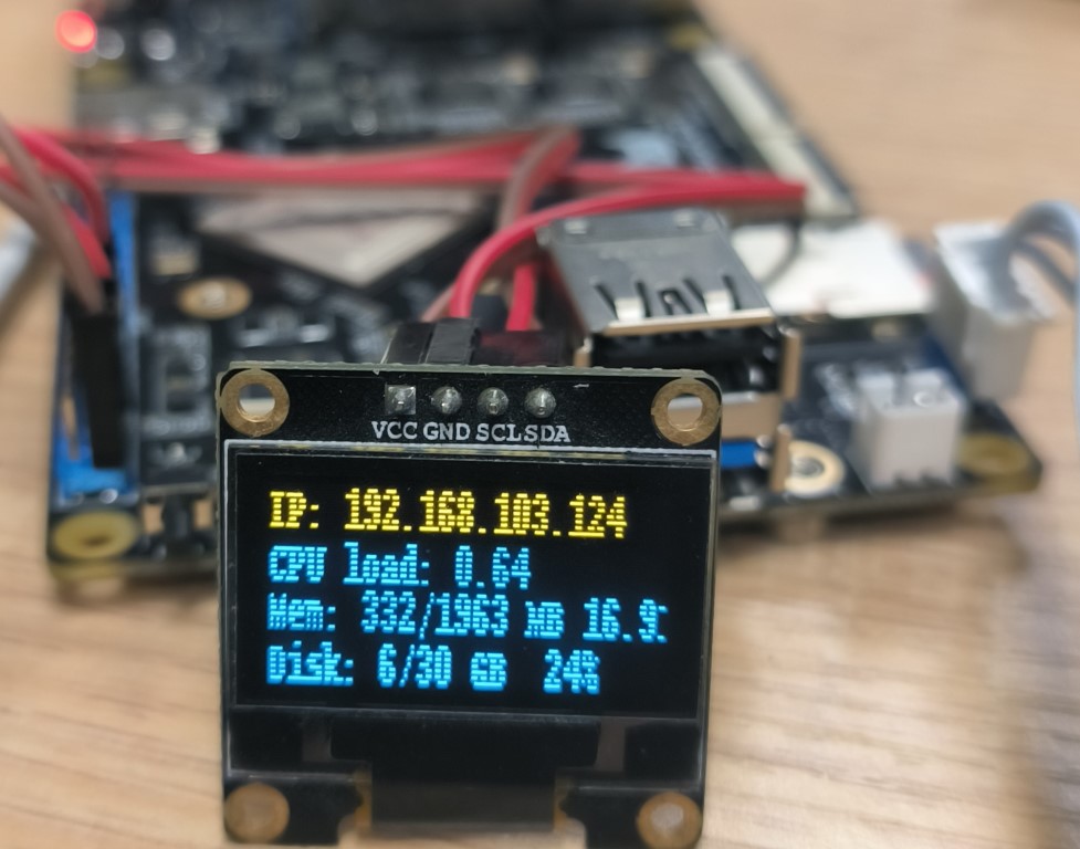
Finally, run any Demo in the terminal to check the effect:
sudo python3 ssd1306_stats.py
It can display information such as the running status of the Lubancat board in real time: