
5. PWM control
Video introduction to this chapter:

“33-PWM Pulse Width Modulation”
https://www.bilibili.com/video/BV1Zu411h7JM/
5.1. pwm pin
Four GPIOs with pwm function are integrated on the LubanCat board
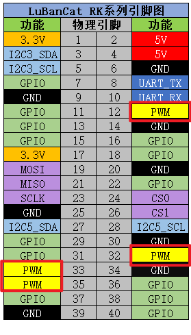
Since the PWM controller of the LubanCat-RK series boards will be different, please use the following table
Board |
Pin12 |
Pin32 |
Pin33 |
Pin35 |
|---|---|---|---|---|
LubanCat-Zero series |
pwm3 |
pwm11 |
pwm8 |
pwm9 |
LubanCat-1 series |
pwm8 |
pwm9 |
pwm10 |
pwm14 |
LubanCat-2 series |
pwm8 |
pwm9 |
pwm10 |
pwm14 |
Specific pins can be viewed — LubanCat-RK series-40pin pin comparison diagram
5.1.1. Enable PWM interface function
The PWM interface is off by default and needs to be enabled before it can be used. Each board has four hardware PWMs, the following enabling operations take PWM8 and PWM9 as examples
5.1.1.1. Method 1
1 2 3 4 5 | #Enter tool configuration
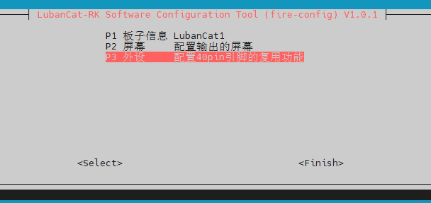
sudo fire-config
#Move the cursor to the position in the picture below
#Press the confirm key to enter the configuration
|
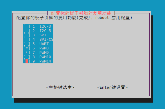
Turn on PWM8 and PWM9
Use the arrow keys to move the cursor to
PWM8.Press “Space” to select PWM8 (appear “*”), as shown below.
Use the arrow keys to move the cursor to
PWM9.Press “Space” to select PWM9 (appear “*”), as shown below.
Press “Enter” to set.
Press “Esc key” to exit to the terminal, run sudo reboot to restart the application.
5.1.1.2. Method 2
Board |
Device Tree Plugin Configuration File |
|---|---|
LubanCat-Zero-W |
uEnvLubanCatZW.txt |
LubanCat-Zero-N |
uEnvLubanCatZN.txt |
LubanCat- 1 |
uEnvLubanCat1.txt |
LubanCat-1N |
uEnvLubanCat1N.txt |
LubanCat-2 |
uEnvLubanCat2.txt |
New version LubanCat-2 |
uEnvLubanCat2-V1.txt |
LubanCat-2N |
uEnvLubanCat2N.txt |
You can open /boot/uEnv/board.txt (board is the name of the board you are using, refer to the table above) to check whether the pwm related device device tree plug-in is enabled.
Edit the file, and remove the comment symbols of the two lines with pwm8 and pwm9, as shown in the figure below:
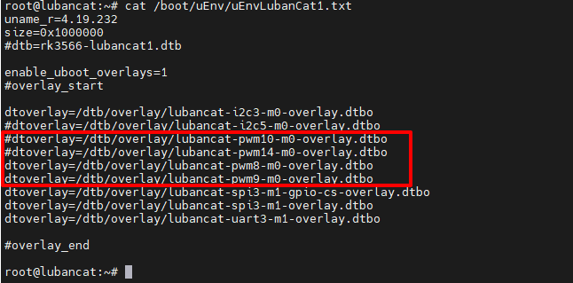
Then reboot to activate the device
注解
If it is restarted by directly unplugging the power supply, the file may not be able to be modified (reason: the file was not synchronized from the memory to the storage device in time, the solution is to enter “sync” on the terminal and then unplug the power to shut down)
5.2. Check the PWM device
After enabling the pwm communication interface, you can use the following command to check whether the pwm is enabled
1 | ls /sys/class/pwm/
|
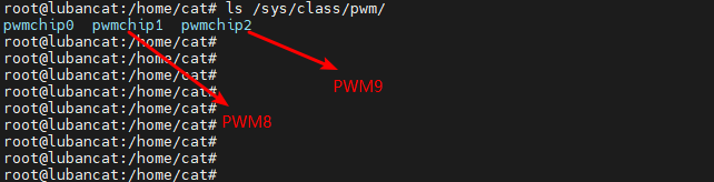
pwmchip0 is the backlight of the screen, the system is enabled by default. When multiple pwm device tree plug-ins are enabled, the smaller the value of the pwm controller, the smaller the pwmchip allocated by the system
1 2 3 4 5 | For example, if I enable pwm8, pwm9, and pwm14 at the same time, the following correspondence will appear
pwm8->pwmchip1
pwm9->pwmchip2
pwm14->pwmchip3
|
5.3. pwm control mode (shell)
The following operation takes pwm8 as an example.
注意
Before operation, you must open the device tree plug-in, restart and enable the pwm8 pin
1 2 3 4 5 6 7 8 9 10 11 12 13 14 15 16 17 | #Export pwm3 to user space
echo 0 > /sys/class/pwm/pwmchip1/export
#Set the pwm period in ns
echo 1000000 > /sys/class/pwm/pwmchip1/pwm0/period
#Set duty cycle
echo 500000 > /sys/class/pwm/pwmchip1/pwm0/duty_cycle
#Set pwm polarity
echo "normal" > /sys/class/pwm/pwmchip1/pwm0/polarity
#Enable pwm
echo 1 > /sys/class/pwm/pwmchip1/pwm0/enable
#Cancel pwm3 export to user space
echo 0 > /sys/class/pwm/pwmchip1/unexport
|
提示
When setting the period and duty_cycle values, you need to pay attention to ensure that the value of period is greater than or equal to the value of duty_cycle under any circumstances.