
3. I2C communication
Video introduction to this chapter:

“31-Use I2C interface on Lubancat”
https://www.bilibili.com/video/BV1Th411T7bd/
This chapter introduces the communication between the I2C bus and external devices in the application layer, and explains the application of the Linux system bus type device driver architecture.
Code repository for this chapter
1 2 3 4 5 6 | #You can skip it if you have obtained it before
#get warehouse
git clone https://gitee.com/LubanCat/lubancat_rk_code_storage.git
#location of the code
lubancat_rk_code_storage/quick_start/i2c
|
This chapter mainly revolves around the LubanCat-RK series boards with 40 pins. The models of the boards are as follow
LubanCat-Zero-W
LubanCat-Zero-N
LubanCat-1
LubanCat-1N
LubanCat-2
LubanCat-2N
3.1. i2c pin
LubanCat-RK series boards have 2 I2C peripherals, namely i2c-3 and i2c-5.
I2C |
pin |
function |
|---|---|---|
I2C3-SCL |
5 |
i2c3 clock signal line |
I2C3-SDA |
3 |
i2c3 data line |
I2C5-SCL |
28 |
Clock signal line of i2c5 |
I2C5-SDA |
27 |
i2c5 data line |
As shown below :
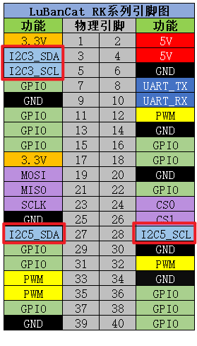
Corresponding to the physical 40pin interface
3.2. Enable IIC communication interface
The IIC interface is disabled by default and needs to be enabled before it can be used
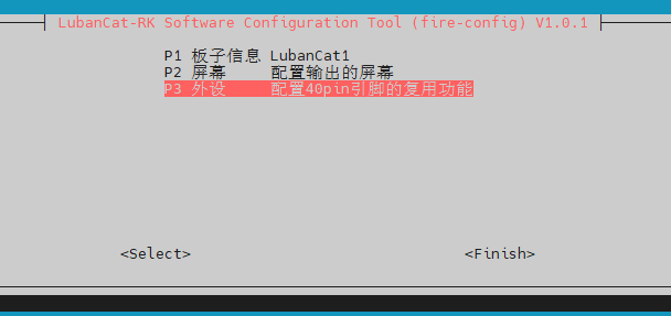
3.2.1. Method 1
1 2 3 4 5 | #Enter tool configuration
sudo fire-config
#Move the cursor to the position in the picture below
#Press the enter key to enter the configuration
|
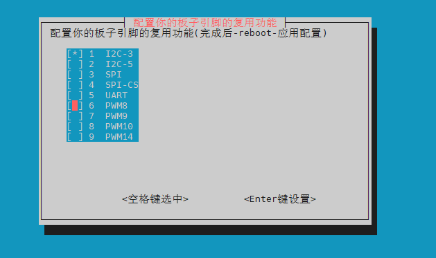
Select the I2C interface you want to open, here is an example to open I2C-3
Use the arrow keys to move the cursor to
I2C-3Press “Space” to select I2C-3 (appears “*” ), as shown below
Press “Enter” to make settings
Press “Esc” to exit to the terminal, run sudo reboot to restart the application
3.2.2. Method 2
Board |
Device Tree Plugin Configuration File |
|---|---|
LubanCat-Zero-W |
uEnvLubanCatZW.txt |
LubanCat-Zero-N |
uEnvLubanCatZN.txt |
LubanCat-1 |
uEnvLubanCat1.txt |
LubanCat-1N |
uEnvLubanCat-1N.txt |
LubanCat-2 |
uEnvLubanCat2.txt |
New version LubanCat-2 |
uEnvLubanCat2-V1.txt |
LubanCat-2N |
uEnvLubanCat2N.txt |
You can open /boot/uEnv/board.txt (board is the name of the board you are using) to check whether the i2c-related device device tree plugin is enabled.
Here, take activating I2C-3 as an example, remove the comment mark of the line with I2C-3, as shown in the figure below:
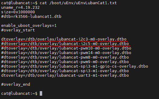
Then reboot to activate the device
注解
If it is restarted by directly unplugging the power supply, there may be files that cannot be modified. ( Reason: The file failed to be synchronized from the internal memory to the storage device in time. The solution is to enter “sync” on the terminal and then unplug the power to shut down )
3.2.3. Check IIC device
You can check whether the i2c bus is turned on with the following command
1 | ls /dev/i2c-*
|
As shown below :
3.3. Connect device
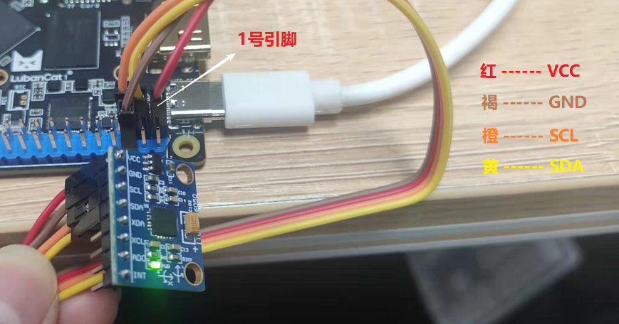
Connect the mpu6050 to the i2c-3 bus, as shown in the figure below
1 2 3 4 5 6 7 | #The board is connected to the mpu6050
Board ------ mpu6050
3.3V(1) ------ VCC
GND(6) ------ GND
SCL(5) ------ SCL
SDA(3) ------ SDA
|
3.4. IIC third-party tools - i2c-tools
Use the i2c-tools toolkit to provide some very convenient tools to debug the I2C bus of the system. You can directly execute the following commands in the terminal of the board to install:
1 | sudo apt install i2c-tools wget gcc -y
|
The commands that can be used after installation are i2cdetect, i2cdump, i2cset and i2cget, which are used to scan devices on the I2C bus, read and write registers of specified devices, etc.
Then check the device mounted on i2c-3, the output is as follows:
1 2 3 4 5 6 7 8 9 10 11 12 13 14 15 | root@lubancat:~# i2cdetect -a 3
WARNING! This program can confuse your I2C bus, cause data loss and worse!
I will probe file /dev/i2c-3.
I will probe address range 0x00-0x7f.
Continue? [Y/n] y
0 1 2 3 4 5 6 7 8 9 a b c d e f
00: -- -- -- -- -- -- -- -- -- -- -- -- -- -- -- --
10: -- -- -- -- -- -- -- -- -- -- -- -- -- -- -- --
20: -- -- -- -- -- -- -- -- -- -- -- -- -- -- -- --
30: -- -- -- -- -- -- -- -- -- -- -- -- -- -- -- --
40: -- -- -- -- -- -- -- -- -- -- -- -- -- -- -- --
50: -- -- -- -- -- -- -- -- -- -- -- -- -- -- -- --
60: -- -- -- -- -- -- -- -- 68 -- -- -- -- -- -- --
70: -- -- -- -- -- -- -- -- -- -- -- -- -- -- -- --
root@lubancat:~# ^C
|
Among them, “68” is the device address of MPU6050, and the commonly used commands are as follows.
1 2 3 4 5 6 7 8 9 10 11 12 13 14 15 16 | #Detect several sets of i2c buses in the current system.
i2cdetect -l
#View devices on the i2c-0 interface.
i2cdetect -a 3
#Read the values of all registers of the specified device.
i2cdump -f -y 3 0x68
#Read the value of a register of the specified IIC device,
as follows to read the value of the 0x01 register in the device whose address is 0x68.
i2cget -f -y 3 0x68 0x01
#Write the value of a certain register of the specified IIC device,
as follows to set the value of the 0x01 register in the device whose address is 0x68 to 0x6f;
i2cset -f -y 3 0x68 0x01 0x6f
|
3.5. Read gyroscope sensor data experiment
3.5.1. Experiment Description
This tutorial will read the raw data of the gyroscope (MPU6050) through the IIC interface. This experiment will take i2c-3 as an example. The operation of i2c-5 is the same as that of i2c-3. Of course, if you don’t have the mpu6050 module, you can operate the i2c device you want to operate by learning how to operate the mpu6050. Read and display the raw data of the MPU6050 approximately every second in the test program.
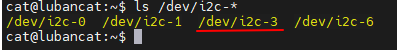
Check the IIC device file to ensure that the IIC 3 interface is enabled
1 2 3 | root@lubancat:~# ls /dev/i2c-*
/dev/i2c-0 /dev/i2c-1 /dev/i2c-3 /dev/i2c-6
root@lubancat:~#
|
Among them, “i2c-3” is the IIC 3 interface bus used by MPU6050.
3.5.2. ioctl function
When writing an application, you need to use the ioctl function to set the i2c related configuration. The function prototype is as follows
1 2 3 | #include <sys/ioctl.h>
int ioctl(int fd, unsigned long request, ...);
|
Among them, the following are commonly used values for terminal request:
I2C_RETRIES |
Set the number of retries when the ACK is not received, the default is 1 |
I2C_TIMEOUT |
Set jiffies with timeout |
I2C_SLAVE |
Set slave address |
I2C_SLAVE_FORCE |
Mandatory setting of slave address |
I2C_TENBIT |
Select address length 0 as 7-bit address, non-zero as 10-bit |
3.5.3. Write application
According to the relevant parameters of ioctl, the interface function related to i2c can be written, and the program to read the original data of mpu6050 is as follows
1 | quick_start/i2c/i2c_mpu6050.c
|
The code is long and easy to copy and paste out of order, you can download the source code we provide i2c_mpu6050.c
1 2 3 4 5 6 7 8 9 10 11 12 13 14 15 16 17 18 19 20 21 22 23 24 25 26 27 28 29 30 31 32 33 34 35 36 37 38 39 40 41 42 43 44 45 46 47 48 49 50 51 52 53 54 55 56 57 58 59 60 61 62 63 64 65 66 67 68 69 70 71 72 73 74 75 76 77 78 79 80 81 82 83 84 85 86 87 88 89 90 91 92 93 94 95 96 97 98 99 100 101 102 103 104 105 106 107 108 109 110 111 112 113 114 115 116 117 118 119 120 121 122 123 124 125 126 127 128 129 130 131 132 133 134 135 136 137 138 139 140 141 142 143 144 145 146 147 148 149 150 151 152 153 154 155 | #include <stdio.h>
#include <stdlib.h>
#include <stdint.h>
#include <unistd.h>
#include <sys/types.h>
#include <sys/stat.h>
#include <fcntl.h>
#include <linux/i2c.h>
#include <linux/i2c-dev.h>
#include <sys/ioctl.h>
/*Register address*/
#define SMPLRT_DIV 0x19
#define PWR_MGMT_1 0x6B
#define CONFIG 0x1A
#define ACCEL_CONFIG 0x1C
#define ACCEL_XOUT_H 0x3B
#define ACCEL_XOUT_L 0x3C
#define ACCEL_YOUT_H 0x3D
#define ACCEL_YOUT_L 0x3E
#define ACCEL_ZOUT_H 0x3F
#define ACCEL_ZOUT_L 0x40
#define GYRO_XOUT_H 0x43
#define GYRO_XOUT_L 0x44
#define GYRO_YOUT_H 0x45
#define GYRO_YOUT_L 0x46
#define GYRO_ZOUT_H 0x47
#define GYRO_ZOUT_L 0x48
//Slave address MPU6050 address
#define Address 0x68
//MPU6050 operation related functions
static int mpu6050_init(int fd,uint8_t addr);
static int i2c_write(int fd, uint8_t addr,uint8_t reg,uint8_t val);
static int i2c_read(int fd, uint8_t addr,uint8_t reg,uint8_t * val);
static short GetData(int fd,uint8_t addr,unsigned char REG_Address);
int main(int argc,char *argv[] )
{
int fd;
fd = I2C_SLAVE;
if(argc < 2){
printf("Wrong use !!!!\n");
printf("Usage: %s [dev]\n",argv[0]);
return -1;
}
fd = open(argv[1], O_RDWR); // open file and enable read and write
if (fd < 0){
printf("Can't open %s \n",argv[1]); // open i2c dev file fail
exit(1);
}
//Initialize MPU6050
mpu6050_init(fd,Address);
while(1){
usleep(1000 * 10);
printf("ACCE_X:%6d\n ", GetData(fd,Address,ACCEL_XOUT_H));
usleep(1000 * 10);
printf("ACCE_Y:%6d\n ", GetData(fd,Address,ACCEL_YOUT_H));
usleep(1000 * 10);
printf("ACCE_Z:%6d\n ", GetData(fd,Address,ACCEL_ZOUT_H));
usleep(1000 * 10);
printf("GYRO_X:%6d\n ", GetData(fd,Address,GYRO_XOUT_H));
usleep(1000 * 10);
printf("GYRO_Y:%6d\n ", GetData(fd,Address,GYRO_YOUT_H));
usleep(1000 * 10);
printf("GYRO_Z:%6d\n\n ", GetData(fd,Address,GYRO_ZOUT_H));
sleep(1);
}
close(fd);
return 0;
}
static int mpu6050_init(int fd,uint8_t addr)
{
i2c_write(fd, addr,PWR_MGMT_1,0x00); //Configure power management, 0x00, start normally
i2c_write(fd, addr,SMPLRT_DIV,0x07); //Set the output frequency division of MPU6050 and set the sampling
i2c_write(fd, addr,CONFIG,0x06); //Configure the digital low-pass filter and frame sync pin
i2c_write(fd, addr,ACCEL_CONFIG,0x01); //Set range and X, Y, Z axis acceleration self-test
return 0;
}
static int i2c_write(int fd, uint8_t addr,uint8_t reg,uint8_t val)
{
int retries;
uint8_t data[2];
data[0] = reg;
data[1] = val;
//Set address length: 0 is a 7-bit address
ioctl(fd,I2C_TENBIT,0);
//Set slave address
if (ioctl(fd,I2C_SLAVE,addr) < 0){
printf("fail to set i2c device slave address!\n");
close(fd);
return -1;
}
//Set the number of retries when no ACK is received
ioctl(fd,I2C_RETRIES,5);
if (write(fd, data, 2) == 2){
return 0;
}
else{
return -1;
}
}
static int i2c_read(int fd, uint8_t addr,uint8_t reg,uint8_t * val)
{
int retries;
//Set address length: 0 is a 7-bit address
ioctl(fd,I2C_TENBIT,0);
//Set slave address
if (ioctl(fd,I2C_SLAVE,addr) < 0){
printf("fail to set i2c device slave address!\n");
close(fd);
return -1;
}
//Set the number of retries when no ACK is received
ioctl(fd,I2C_RETRIES,5);
if (write(fd, ®, 1) == 1){
if (read(fd, val, 1) == 1){
return 0;
}
}
else{
return -1;
}
}
static short GetData(int fd,uint8_t addr,unsigned char REG_Address)
{
char H, L;
i2c_read(fd, addr,REG_Address, &H);
usleep(1000);
i2c_read(fd, addr,REG_Address + 1, &L);
return (H << 8) +L;
}
|
Save and exit, then compile and run
1 2 3 | gcc i2c_mpu6050.c -o mpu6050
sudo ./mpu6050 /dev/i2c-3
|
Results as shown below:
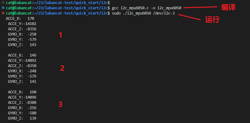
Three data collection
3.6. More
For more information about rk-i2c drivers and GPIO analog I2C, please check: rk open source manual /Common/I2C
3.7. References
This document mainly provides a quick start for users with certain experience. For beginners, you can view the following documents:
rk open source information (github): 《open source handbook》