
8. RS485
目前硬件上支持RS485的有以下板卡:
LubanCat-1金手指底板(含有RS485x2)
LubanCat-1BTB底板(含有RS485x2)
LubanCat-1H底板(含有RS485x2)
LubanCat-1HS底板(含有RS485x2)
LubanCat-2金手指底板(含有RS485x2)
LubanCat-2BTB底板(含有RS485x2)
LubanCat-2H底板(含有RS485x2)
8.1. 硬件标识和引脚定义
8.1.1. 硬件标识
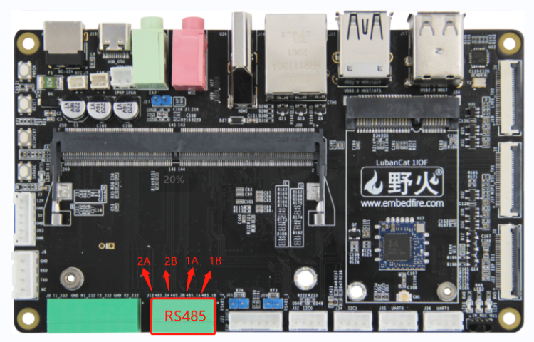
金手指和btb核心板只是封装接口不同,功能引脚和配置完全一样,下面以金手指底板为例具体的引脚定义可以参考背面的丝印。
LubanCat-1金手指底板:
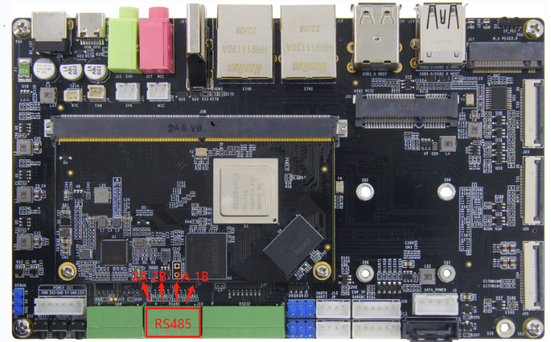
LubanCat-2金手指底板:
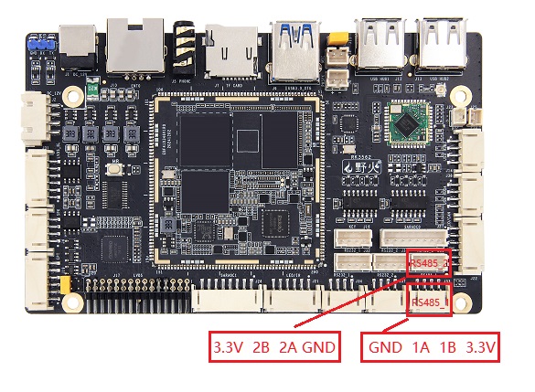
LubanCat-1HS底板:
8.1.2. 引脚定义
LubanCat-1金手指/BTB底板
485引脚 |
对应串口 |
流控引脚 |
RS485-1 |
UART1-M0 |
GPIO2_PB5 |
RS485-2 |
UART6-M0 |
GPIO2_PB6 |
LubanCat-1H底板
485引脚 |
对应串口 |
流控引脚 |
RS485-1 |
UART0-M0 |
GPIO2_PB1 |
RS485-2 |
UART3-M0 |
GPIO2_PB2 |
LubanCat-1HS底板
485引脚 |
对应串口 |
流控引脚 |
RS485-1 |
UART8-M0 |
GPIO3_PB6 |
RS485-2 |
UART9-M1 |
GPIO3_PC1 |
LubanCat-2金手指/BTB底板
485引脚 |
对应串口 |
流控引脚 |
RS485-1 |
UART3-M1 |
GPIO2_PD2 |
RS485-2 |
UART4-M1 |
GPIO2_PD3 |
LubanCat-2H底板
485引脚 |
对应串口 |
流控引脚 |
RS485-1 |
UART9-M0 |
GPIO3_PD5 |
RS485-2 |
UART8-M1 |
GPIO3_PA7 |
8.2. 软件配置
重要
野火2023年11月或者更新的镜像已支持RS485驱动层换流,不需要再在应用层手动换流,使用方法和普通串口一样,十分简单,因此建议使用新镜像或更新内核,使用驱动层换流。
8.2.1. 使用驱动层换流
这里以开启RS485-1为例,开启和关闭,rs485对应的 rs485插件 ,支持RS485的板卡操作相同,只是设备树插件名字稍有差异。
8.2.1.1. 修改配置文件
1 2 | #修改配置文件
sudo vi /boot/uEnv/uEnv.txt
|
8.2.1.1.1. 开启设备树插件方法
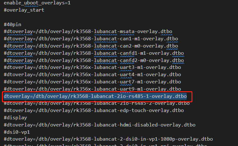
这里以LubanCat-2金手指/BTB底板 开启RS485-1 为例:
把
#dtoverlay=/dtb/overlay/rk3568-lubancat-2io-rs485-1-overlay.dtbo前面的#删除,如下图。
8.2.1.1.2. 关闭设备树插件方法
这里以LubanCat-2金手指/BTB底板 关闭RS485-1 为例:
在
dtoverlay=/dtb/overlay/rk3568-lubancat-2io-rs485-1-overlay.dtbo前面添加#,如下图。

修改完配置文件后需要重启生效。
1 2 | #重启
sudo reboot
|
8.2.2. 使用应用层换流
这里以开启LubanCat-2金手指/BTB底板RS485-1为例,开启和关闭rs485对应的 串口插件 ,支持RS485的板卡操作相同,只是设备树插件名字稍有差异,需要根据实际对应的串口进行修改。
8.2.2.1. 修改配置文件
1 2 | #修改配置文件
sudo vi /boot/uEnv/uEnv.txt
|
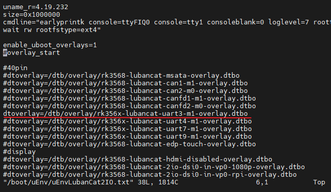
8.2.2.1.1. 开启设备树插件方法
这里以LubanCat-2金手指/BTB底板为例:
把
#dtoverlay=/dtb/overlay/rk356x-lubancat-uart3-m1-overlay.dtbo前面的#删除,如下图。
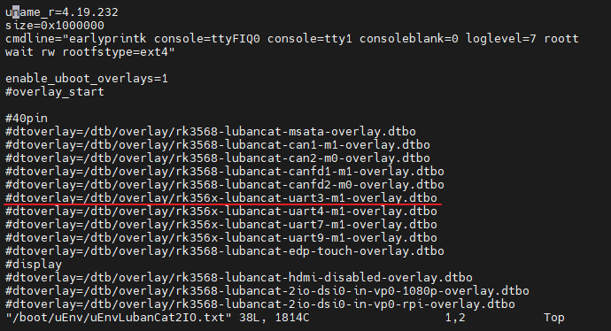
8.2.2.1.2. 关闭设备树插件方法
这里以LubanCat-2金手指/BTB底板为例:
在
dtoverlay=/dtb/overlay/rk356x-lubancat-uart3-m1-overlay.dtbo前面添加#,如下图。
修改完配置文件后需要重启生效。
1 2 | #重启
sudo reboot
|
8.2.3. 使用方法
重要
使用驱动层换流不需要再在应用层手动换流,使用应用层换流则需要在应用层手动控制流控引脚电平实现换流。
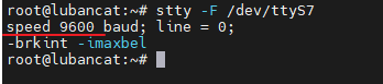
这里以LubanCat-2金手指/BTB底板RS485-1为例,该底板RS485-1对应串口是UART3-M1。
LubanCat-2金手指/BTB底板RS485-1对应的设备树插件使能后,在/dev目录下生成ttyS3设备文件,用stty工具查询其通信参数。
1 2 3 4 | #需要在root用户下运行
#在板卡的终端执行如下命令
stty -F /dev/ttyS3
|
如下图:
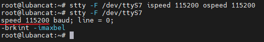
8.2.3.1. 修改串口波特率
1 2 3 4 | #需要在root用户下运行
#设置通讯速率,其中ispeed为输入速率,ospeed为输出速率
stty -F /dev/ttyS3 ispeed 115200 ospeed 115200
|
如下图:
8.2.3.3. 使用驱动层换流的通讯方法
1 2 3 4 5 6 7 8 | #需要在root用户下运行
#操作和普通串口一样,直接收发即可
#发送消息
echo "I'm lubancat" > /dev/ttyS3
#接收消息
cat /dev/ttyS3
|
除了这种方法外,还可以使用minicom,具体方法可以参考下列文章 串口章节 。
8.2.3.4. 使用应用层换流的通讯方法
使用应用层换流需要在应用层手动控制流控引脚电平实现换流,如果想要发送信息,需要把发送引脚拉高,如果想要接收信息,需要把发送引脚拉低,具体流控引脚根据实际板卡而定。
板卡 |
RS485-1流控引脚 |
RS485-2流控引脚 |
LubanCat-1金手指/BTB底板 |
GPIO2_PB5 |
GPIO2_PB6 |
LubanCat-1H底板 |
GPIO2_PB1 |
GPIO2_PB2 |
LubanCat-1HS底板 |
GPIO3_PB6 |
GPIO3_PC1 |
LubanCat-2金手指/BTB底板 |
GPIO2_PD2 |
GPIO2_PD3 |
LubanCat-2H |
GPIO3_PD5 |
GPIO3_PA7 |
8.2.3.4.1. GPIO的操作方法
引脚编号此处不作过多说明,参考 GPIO控制章节
1、使用sysfs
以LubanCat-2金手指/BTB底板RS485-1的流控引脚为例,RS485-2的引脚的操作类似。
1 2 3 4 5 6 7 8 9 10 11 12 13 14 15 16 17 | #需要在root用户下运行
#使能引脚
echo 90 > /sys/class/gpio/export
#设置引脚为输出模式
echo out > /sys/class/gpio/gpio90/direction
#设置引脚为低电平
echo 0 > /sys/class/gpio/gpio90/value
#流控引脚为低时,数据接收
cat /dev/ttyS3
#设置引脚为高电平
echo 1 > /sys/class/gpio/gpio90/value
#流控引脚为高时,数据发送
echo "I'm lubancat" > /dev/ttyS3
|
2、使用gpiod
1 2 3 4 5 6 7 8 9 10 11 | #需要在root用户下运行
#设置RS485-1的引脚为高电平
gpioset 2 26=1
#流控引脚为高时,数据发送
echo "I'm lubancat" > /dev/ttyS3
#设置RS485-1的引脚为低电平
gpioset 2 26=0
#流控引脚为低时,数据接收
cat /dev/ttyS3
|
8.3. 自检测试
该测试需要把两个RS485引脚用线相连接。
RS485-1A |
连接 |
RS485-2A |
RS485-1B |
连接 |
RS485-2B |
然后需要同时打开RS485-1和RS485-2对应的设备树插件。
8.3.1. 使用驱动层换流自检测试
根据前面介绍的使能RS485对应的 RS485设备树插件 并且正确将RS485-1和RS485-2相连接后,可进行自检测试。
以LubanCat-2金手指/BTB底板为例:
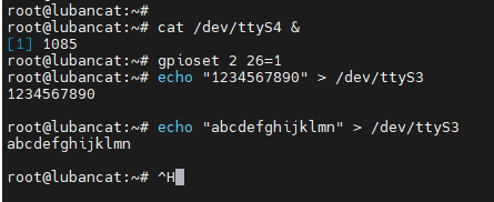
1 2 3 4 5 6 7 8 | #需要在root用户下运行
#RS485-2后台接收数据
cat /dev/ttyS4 &
#RS485-1发送消息
echo "1234567890" > /dev/ttyS3
echo "abcdefghijklmn" > /dev/ttyS3
|
发送完成就可以看到有接收到消息了,如下图所示。

提示
驱动层换流只支持中断模式,不支持DMA,以上提示DMA失败使用中断模式是正常的。UART使用DMA传输模式只有在数据量很大时才会产生较为明显的减轻CPU负载的效果。一般情况下,和使用中断传输模式相比,UART使用DMA传输模式并不一定能提高数据传输速度。一方面,CPU性能都很高,传输瓶颈在外设。另一方面,启动DMA需要消耗额外的资源,并且由于UART数据存在长度不确定的特性,会使DMA传输效率下降。
如果想结束后台运行的 cat /dev/ttyS4 &,参照以下操作。
1 | pkill cat
|
RS485-1接收&RS485-2发送的方法与上述方法类似,只是将串口编号进行对调,可以自行修改操作。
8.3.2. 使用应用层换流自检测试
根据前面介绍的使能RS485对应的 串口设备树插件 并且正确将RS485-1和RS485-2相连接后,可进行自检测试。
以LubanCat-2金手指/BTB底板为例:
1 2 3 4 5 6 7 8 9 10 11 | #需要在root用户下运行
#RS485-2流控脚拉低,数据接收
gpioset 2 27=0
#RS485-2后台接收
cat /dev/ttyS4 &
#RS485-1流控脚拉高,数据发送
gpioset 2 26=1
#RS485-1发送消息
echo "1234567890" > /dev/ttyS3
|
发送完成就可以看到有接收到消息了,如下图所示。
如果想结束后台运行的 cat /dev/ttyS4 &,参照以下操作。
1 | pkill cat
|
RS485-1接收&RS485-2发送的方法与上述方法类似,只是将串口编号进行对调以及修改流控引脚电平,可以自行修改操作。
8.4. C程序收发示例
8.4.2. 使用应用层换流C程序收发示例
此处示例在前面自检测试基础上编译C程序进行收发测试,如需实现其他功能可自行参考修改。
此处示例驱动层换流的也可以参考,只需将流控部分代码去掉即可。
根据前面介绍的使能RS485对应的设备树插件并且正确将RS485-1和RS485-2相连接后,可进行后续步骤。
以LubanCat-2金手指/BTB底板为例:
1 2 3 4 5 6 7 8 9 10 11 12 13 14 15 16 17 18 19 20 21 22 23 24 25 26 27 28 29 30 31 32 33 34 35 36 37 38 39 40 41 42 43 44 45 46 47 48 49 50 51 52 53 54 55 56 57 58 59 60 61 62 63 64 65 66 67 68 69 70 71 72 73 74 75 76 77 78 79 80 81 82 83 84 85 86 87 88 89 90 91 92 93 94 95 96 97 98 99 100 101 102 103 104 105 106 107 108 109 110 111 112 113 114 115 116 117 118 119 120 121 122 123 124 125 126 127 128 129 130 131 132 133 134 135 136 137 138 139 140 141 142 143 144 145 146 147 148 149 150 151 152 153 154 155 156 157 158 159 160 161 162 163 164 165 166 167 168 169 170 171 172 173 174 175 176 177 178 179 180 181 182 183 184 185 186 187 188 189 190 191 192 193 194 195 196 197 198 199 200 201 202 203 204 205 206 207 208 209 210 211 212 213 214 215 216 217 218 219 220 221 222 223 224 225 226 227 228 229 230 231 232 233 234 235 236 237 238 239 240 241 242 243 244 245 246 247 248 249 250 251 252 253 254 255 | #include <sys/types.h>
#include <sys/stat.h>
#include <fcntl.h>
#include <stdio.h>
#include <stdlib.h>
#include <string.h>
#include <stdint.h>
#include <unistd.h>
#include <termios.h>
#define SERVER_GPIO_INDEX "90" //流控引脚对应编号
const char default_path[] = "/dev/ttyS3"; //rs485-1对应的串口
/*
*串口配置成功返回0,失败返回-1;
*/
int set_uart(int fd,int nSpeed, int nBits, char nEvent, int nStop);
static int _server_ioctl_init(void)
{
int fd;
//index config
fd = open("/sys/class/gpio/export", O_WRONLY);
if(fd < 0)
return 1;
write(fd, SERVER_GPIO_INDEX, strlen(SERVER_GPIO_INDEX));
close(fd);
//direction config
fd = open("/sys/class/gpio/gpio" SERVER_GPIO_INDEX "/direction", O_WRONLY);
if(fd < 0)
return 2;
write(fd, "out", strlen("out"));
close(fd);
return 0;
}
static int _server_ioctl_on(void)
{
int fd;
fd = open("/sys/class/gpio/gpio" SERVER_GPIO_INDEX "/value", O_WRONLY);
if(fd < 0){
printf("_server_ioctl_open error\n");
return 1;
}
write(fd, "1", 1);
close(fd);
return 0;
}
static int _server_ioctl_off(void)
{
int fd;
fd = open("/sys/class/gpio/gpio" SERVER_GPIO_INDEX "/value", O_WRONLY);
if(fd < 0)
return 1;
write(fd, "0", 1);
close(fd);
return 0;
}
static void _modbus_rtu_server_ioctl(int on)
{
if (on) {
_server_ioctl_on();
} else {
_server_ioctl_off();
}
}
static int _server_ioctl_exit(void)
{
int fd;
fd = open("/sys/class/gpio/uexport", O_WRONLY);
if(fd < 0)
return 1;
write(fd, SERVER_GPIO_INDEX, strlen(SERVER_GPIO_INDEX));
close(fd);
}
int main(int argc,char *argv[])
{
int fd;
int res;
char *path;
//char buf[1024] = "Embedfire 485 send test.\n";
char buf[1024] = "1111111\n";
char buf1[1024];
int i;
if(argc > 1)
{
path = argv[1];
}
else
{
path = (char *)default_path;
}
fd = open(path,O_RDWR);
if(fd < 0)
{
perror(path);
exit(-1);
}
if( set_uart(fd,115200,8,'n',1) )
{
printf("set uart error\n");
}
_server_ioctl_init();
for(i=0;i<100;i++){
//485-1发送
_modbus_rtu_server_ioctl(1);
write(fd, buf, strlen(buf));
printf("485-1 Send data, res = %d bytes data: %s\r\n",strlen(buf), buf);
usleep(10000); // 10毫秒
//sleep(1);
//485-1读取
_modbus_rtu_server_ioctl(0);
memset(buf1,0,1024);
res = read(fd, buf1, 1024);
if(res > 0)
{
printf("485-1 Read data, res = %d bytes data: %s\r\n",res, buf1);
}
printf("cycle index is %d\r\n",i);
usleep(10000); // 10毫秒
//sleep(1);
}
_server_ioctl_exit();
close(fd);
return 0;
}
int set_uart(int fd,int nSpeed, int nBits, char nEvent, int nStop)
{
struct termios opt;
//清空串口接收缓冲区
tcflush(fd, TCIOFLUSH);
//获取串口配置参数
tcgetattr(fd, &opt);
opt.c_cflag &= (~CBAUD); //清除数据位设置
opt.c_cflag &= (~PARENB); //清除校验位设置
//opt.c_iflag |= IGNCR; //忽略接收数据中的'\r'字符,在windows中换行为'\r\n'
opt.c_iflag &= (~ICRNL); //不将'\r'转换为'\n'
opt.c_lflag &= (~ECHO); //不使用回显
//设置波特率
switch(nSpeed)
{
case 2400:
cfsetspeed(&opt,B2400);
break;
case 4800:
cfsetspeed(&opt,B4800);
break;
case 9600:
cfsetspeed(&opt,B9600);
break;
case 38400:
cfsetspeed(&opt,B38400);
break;
case 115200:
cfsetspeed(&opt,B115200);
break;
default:
return -1;
}
//设置数据位
switch(nBits)
{
case 7:
opt.c_cflag |= CS7;
break;
case 8:
opt.c_cflag |= CS8;
break;
default:
return -1;
}
//设置校验位
switch(nEvent)
{
//无奇偶校验
case 'n':
case 'N':
opt.c_cflag &= (~PARENB);
break;
//奇校验
case 'o':
case 'O':
opt.c_cflag |= PARODD;
break;
//偶校验
case 'e':
case 'E':
opt.c_cflag |= PARENB;
opt.c_cflag &= (~PARODD);
break;
default:
return -1;
}
//设置停止位
switch(nStop)
{
case 1:
opt.c_cflag &= ~CSTOPB;
break;
case 2:
opt.c_cflag |= CSTOPB;
break;
default:
return -1;
}
//设置串口
tcsetattr(fd,TCSANOW,&opt);
return 0;
}
|
1 2 3 4 5 6 7 8 9 10 11 12 13 14 15 16 17 18 19 20 21 22 23 24 25 26 27 28 29 30 31 32 33 34 35 36 37 38 39 40 41 42 43 44 45 46 47 48 49 50 51 52 53 54 55 56 57 58 59 60 61 62 63 64 65 66 67 68 69 70 71 72 73 74 75 76 77 78 79 80 81 82 83 84 85 86 87 88 89 90 91 92 93 94 95 96 97 98 99 100 101 102 103 104 105 106 107 108 109 110 111 112 113 114 115 116 117 118 119 120 121 122 123 124 125 126 127 128 129 130 131 132 133 134 135 136 137 138 139 140 141 142 143 144 145 146 147 148 149 150 151 152 153 154 155 156 157 158 159 160 161 162 163 164 165 166 167 168 169 170 171 172 173 174 175 176 177 178 179 180 181 182 183 184 185 186 187 188 189 190 191 192 193 194 195 196 197 198 199 200 201 202 203 204 205 206 207 208 209 210 211 212 213 214 215 216 217 218 219 220 221 222 223 224 225 226 227 228 229 230 231 232 233 234 235 236 237 238 239 240 241 242 243 244 245 246 247 248 249 250 251 252 253 254 | #include <sys/types.h>
#include <sys/stat.h>
#include <fcntl.h>
#include <stdio.h>
#include <stdlib.h>
#include <string.h>
#include <stdint.h>
#include <unistd.h>
#include <termios.h>
#define SERVER_GPIO_INDEX "91" //流控引脚的对应编号
const char default_path[] = "/dev/ttyS4"; //rs485-2对应的串口
/*
*串口配置成功返回0,失败返回-1;
*/
int set_uart(int fd,int nSpeed, int nBits, char nEvent, int nStop);
static int _server_ioctl_init(void)
{
int fd;
//index config
fd = open("/sys/class/gpio/export", O_WRONLY);
if(fd < 0)
return 1;
write(fd, SERVER_GPIO_INDEX, strlen(SERVER_GPIO_INDEX));
close(fd);
//direction config
fd = open("/sys/class/gpio/gpio" SERVER_GPIO_INDEX "/direction", O_WRONLY);
if(fd < 0)
return 2;
write(fd, "out", strlen("out"));
close(fd);
return 0;
}
static int _server_ioctl_on(void)
{
int fd;
fd = open("/sys/class/gpio/gpio" SERVER_GPIO_INDEX "/value", O_WRONLY);
if(fd < 0)
return 1;
write(fd, "1", 1);
close(fd);
return 0;
}
static int _server_ioctl_off(void)
{
int fd;
fd = open("/sys/class/gpio/gpio" SERVER_GPIO_INDEX "/value", O_WRONLY);
if(fd < 0)
return 1;
write(fd, "0", 1);
close(fd);
return 0;
}
static void _modbus_rtu_server_ioctl(int on)
{
if (on) {
_server_ioctl_on();
} else {
_server_ioctl_off();
}
}
static int _server_ioctl_exit(void)
{
int fd;
fd = open("/sys/class/gpio/uexport", O_WRONLY);
if(fd < 0)
return 1;
write(fd, SERVER_GPIO_INDEX, strlen(SERVER_GPIO_INDEX));
close(fd);
}
int main(int argc,char *argv[])
{
int fd;
int res;
char *path;
char buf[1024] = "0000000\n";;
char buf1[1024];
int i;
if(argc > 1)
{
path = argv[1];
}
else
{
path = (char *)default_path;
}
fd = open(path,O_RDWR);
if(fd < 0)
{
perror(path);
exit(-1);
}
if( set_uart(fd,115200,8,'n',1) )
{
printf("set uart error\n");
}
_server_ioctl_init();
for(i=0;i<100;i++){
//485-2读取
_modbus_rtu_server_ioctl(0);
memset(buf1,0,1024);
res = read(fd, buf1, 1024);
if(res > 0)
{
printf("485-2 Read data, res = %d bytes data: %s\r\n",res, buf1);
}
usleep(10000); // 10毫秒
//sleep(1);
//485-2发送
_modbus_rtu_server_ioctl(1);
write(fd, buf, strlen(buf));
printf("485-2 Send data, res = %d bytes data: %s\r\n",strlen(buf), buf);
printf("cycle index is %d\r\n",i);
usleep(10000); // 10毫秒
//sleep(1);
}
_server_ioctl_exit();
close(fd);
return 0;
}
int set_uart(int fd,int nSpeed, int nBits, char nEvent, int nStop)
{
struct termios opt;
//清空串口接收缓冲区
tcflush(fd, TCIOFLUSH);
//获取串口配置参数
tcgetattr(fd, &opt);
opt.c_cflag &= (~CBAUD); //清除数据位设置
opt.c_cflag &= (~PARENB); //清除校验位设置
//opt.c_iflag |= IGNCR; //忽略接收数据中的'\r'字符,在windows中换行为'\r\n'
opt.c_iflag &= (~ICRNL); //不将'\r'转换为'\n'
opt.c_lflag &= (~ECHO); //不使用回显
//设置波特率
switch(nSpeed)
{
case 2400:
cfsetspeed(&opt,B2400);
break;
case 4800:
cfsetspeed(&opt,B4800);
break;
case 9600:
cfsetspeed(&opt,B9600);
break;
case 38400:
cfsetspeed(&opt,B38400);
break;
case 115200:
cfsetspeed(&opt,B115200);
break;
default:
return -1;
}
//设置数据位
switch(nBits)
{
case 7:
opt.c_cflag |= CS7;
break;
case 8:
opt.c_cflag |= CS8;
break;
default:
return -1;
}
//设置校验位
switch(nEvent)
{
//无奇偶校验
case 'n':
case 'N':
opt.c_cflag &= (~PARENB);
break;
//奇校验
case 'o':
case 'O':
opt.c_cflag |= PARODD;
break;
//偶校验
case 'e':
case 'E':
opt.c_cflag |= PARENB;
opt.c_cflag &= (~PARODD);
break;
default:
return -1;
}
//设置停止位
switch(nStop)
{
case 1:
opt.c_cflag &= ~CSTOPB;
break;
case 2:
opt.c_cflag |= CSTOPB;
break;
default:
return -1;
}
//设置串口
tcsetattr(fd,TCSANOW,&opt);
return 0;
}
|
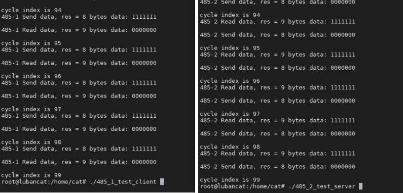
8.4.2.1. 编译程序
1 2 | gcc rs485_1_test_client.c -o rs485_1_test_client
gcc rs485_2_test_server.c -o rs485_2_test_server
|
8.4.2.2. 运行测试
打开两个终端,分别运行两测试程序。终端可以是一个串口终端一个ssh终端,或者都使用ssh。
在终端1执行:
1 | sudo ./rs485_2_test_server
|
在终端2执行:
1 | sudo ./rs485_1_test_client
|
效果如下图所示,485-1和485-2相互收发100次,如果需要发送其他数据,可能需要调整发送和接收数据间的间隔时间,自行测试。
8.5. libmodbus简介
libmodbus是一个与使用modbus协议的设备进行数据发送/接收的库,它包含各种后端(backends)通过不同网络进行通信。 (例如,RTU模式下的串口、485总线或TCP / IPv6中的以太网)。 libmodbus还提供了较低通信层的抽象,并在所有支持的平台上提供相同的API。
libmodbus是开源的,它遵循 LGPL v2.1 开源协议,这个协议没有GPL协议那么严格, 简单来说,只要你不修改libmodbus库里面的东西(只调用、链接该库),你是可以闭源你的代码的,也可以用于商业用途,这一点非常好的。
官方代码仓库位于:https://github.com/stephane/libmodbus
提示
如果使用驱动层换流只需对官方代码进行小修改,将串口改为实际串口即可,如果使用应用层换流需要配置rts引脚,野火也提供了示例测试,可进行参考。
8.5.1. 使用驱动层换流
8.5.1.1. 前期准备
根据前面介绍的使能RS485对应的 RS485设备树插件 并且正确将RS485-1和RS485-2相连接后,可进行后续步骤。
开发准备,在开发板系统上安装libmodbus-dev和一些编译工具。
1 2 | sudo apt update
sudo apt install gcc make git autoconf libtool automake
|
1、拉取libmodbus源码并修改
1 | git clone https://github.com/stephane/libmodbus.git
|
拉取下来后看到本地有libmodbus文件夹,我们进入 libmodbus/tests目录下,该目录下存放了很多测试程序,此处我们使用unit-test-server.c、unit-test-client.c进行测试。
修改为使用使用的接口,以鲁班猫2金手指/btb底板为例:
打开libmodbus/tests/unit-test-server.c,将代码第57行和第76行的/dev/ttyUSB0修改为实际使用的串口,鲁班猫2金手指/btb底板rs485-1对应/dev/ttyS3
1 2 3 4 5 6 7 8 | #将libmodbus/tests/unit-test-server.c的第57行和第76行定义的接口修改为实际的接口
...
printf("Eg. tcp 127.0.0.1 or rtu /dev/ttyS3\n\n");
...
...
ip_or_device = "/dev/ttyS3";
...
|
打开libmodbus/tests/unit-test-client.c,将代码第93行和第112行的/dev/ttyUSB1修改为实际使用的串口,鲁班猫2金手指/btb底板rs485-2对应/dev/ttyS4
1 2 3 4 5 6 7 8 | #将libmodbus/tests/unit-test-client.c的第93行和第112行定义的接口修改为实际的接口
...
printf("Eg. tcp 127.0.0.1 or rtu /dev/ttyS4\n\n");
...
...
ip_or_device = "/dev/ttyS4";
...
|
2、编译程序
进入 libmodbus最上层目录 下,运行它提供的脚本,它主要是自动生成一些用于配置的文件。
1 | ./autogen.sh
|
打印消息如下
1 2 3 4 5 6 7 8 9 10 11 | configure.ac:33: installing 'build-aux/compile'
configure.ac:56: installing 'build-aux/config.guess'
configure.ac:56: installing 'build-aux/config.sub'
configure.ac:32: installing 'build-aux/install-sh'
configure.ac:32: installing 'build-aux/missing'
src/Makefile.am: installing 'build-aux/depcomp'
parallel-tests: installing 'build-aux/test-driver'
------------------------------------------------------
Initialized build system. You can now run ./configure
------------------------------------------------------
|
运行完毕后,接着运行 configure 去配置编译相关的信息。
1 | ./configure
|
最后打印信息如下
1 2 3 4 5 6 7 8 9 10 11 12 13 14 15 16 | config.status: executing depfiles commands
config.status: executing libtool commands
libmodbus 3.1.10
===============
prefix: /usr/local
sysconfdir: ${prefix}/etc
libdir: ${exec_prefix}/lib
includedir: ${prefix}/include
compiler: gcc
cflags: -g -O2
ldflags:
tests: yes
|
运行上一步之后,在当前目录下将产生 Makefile 文件,使用 make 命令编译即可:
1 | make
|
在编译完成后,在 tests 目录下你会发现有很多可执行的文件,比如我们稍后要运行的程序 unit-test-server、unit-test-client:
1 2 3 4 5 6 7 8 9 10 11 12 | root@lubancat:~/libmodbus/tests# ls
LICENSE bandwidth-server-one unit-test-client.c
Makefile bandwidth-server-one.c unit-test-client.o
Makefile.am bandwidth-server-one.o unit-test-server
Makefile.in random-test-client unit-test-server.c
README.md random-test-client.c unit-test-server.o
bandwidth-client random-test-client.o unit-test.h
bandwidth-client.c random-test-server unit-test.h.in
bandwidth-client.o random-test-server.c unit-tests.sh
bandwidth-server-many-up random-test-server.o version
bandwidth-server-many-up.c stamp-h2 version.c
bandwidth-server-many-up.o unit-test-client version.o
|
3、运行程序
打开两个终端,一个用于运行服务端一个用于运行客户端。如下所示
在终端1中执行:
1 | ./unit-test-server rtu
|
在终端2中执行:
1 | ./unit-test-client rtu
|
在 client 终端中最终打印:
1 2 3 4 5 6 7 8 9 10 11 12 13 14 15 16 17 18 19 20 | [11][0F][01][60][00][00][00][02][2B][00][01][00][64][59][63]
* try function 0xF: write 0 values: Waiting for a confirmation...
<11><8F><03><05><F4>
OK
[11][0F][01][60][07][B0][06][02][2B][00][01][00][64][12][27]
* try function 0xF: write 1968 values: Waiting for a confirmation...
<11><8F><03><05><F4>
OK
[11][42][00][00][00][00][7B][55]
Waiting for a confirmation...
<11><C2><01><B1><65>
Return an exception on unknown function code: OK
TEST INVALID INITIALIZATION:
The device string is empty
OK
The baud rate value must not be zero
OK
ALL TESTS PASS WITH SUCCESS.
|
以上只是测试使用,关于具体用法请读者参考官方说明自行研究。
8.5.2. 使用应用层层换流
8.5.2.1. 前期准备
根据前面介绍的使能RS485对应的 串口设备树插件 并且正确将RS485-1和RS485-2相连接后,可进行后续步骤。
开发准备,在开发板系统上安装libmodbus-dev和一些编译工具。
1 2 | sudo apt update
sudo apt install gcc git libmodbus-dev pkg-config
|
8.5.2.2. 程序
以鲁班猫2金手指/btb底板为例,其他底板需要自行修改流控引脚编号以及实际的串口接口。
1.服务端程序
1 2 3 4 5 6 7 8 9 10 11 12 13 14 15 16 17 18 19 20 21 22 23 24 25 26 27 28 29 30 31 32 33 34 35 36 37 38 39 40 41 42 43 44 45 46 47 48 49 50 51 52 53 54 55 56 57 58 59 60 61 62 63 64 65 66 67 68 69 70 71 72 73 74 75 76 77 78 79 80 81 82 83 84 85 86 87 88 89 90 91 92 93 94 95 96 97 98 99 100 101 102 103 104 105 106 107 108 109 110 111 112 113 114 115 116 117 118 119 120 121 122 123 124 125 126 127 128 129 130 131 | #include <stdio.h>
#include <unistd.h>
#include <string.h>
#include <stdlib.h>
#include <errno.h>
#include <modbus.h>
#include <sys/stat.h>
#include <fcntl.h>
#define SERVER_GPIO_INDEX "90" //485-1的换流引脚
#define SERVER_ID 17
const uint16_t UT_REGISTERS_TAB[] = { 0x0A, 0x0E, 0x0A, 0x1B,0x0A};
static int _server_ioctl_init(void)
{
int fd;
//index config
fd = open("/sys/class/gpio/export", O_WRONLY);
if(fd < 0)
return 1;
write(fd, SERVER_GPIO_INDEX, strlen(SERVER_GPIO_INDEX));
close(fd);
//direction config
fd = open("/sys/class/gpio/gpio" SERVER_GPIO_INDEX "/direction", O_WRONLY);
if(fd < 0)
return 2;
write(fd, "out", strlen("out"));
close(fd);
return 0;
}
static int _server_ioctl_on(void)
{
int fd;
fd = open("/sys/class/gpio/gpio" SERVER_GPIO_INDEX "/value", O_WRONLY);
if(fd < 0)
return 1;
write(fd, "1", 1);
close(fd);
return 0;
}
static int _server_ioctl_off(void)
{
int fd;
fd = open("/sys/class/gpio/gpio" SERVER_GPIO_INDEX "/value", O_WRONLY);
if(fd < 0)
return 1;
write(fd, "0", 1);
close(fd);
return 0;
}
static void _modbus_rtu_server_ioctl(modbus_t *ctx, int on)
{
if (on) {
_server_ioctl_on();
} else {
_server_ioctl_off();
}
}
int main(int argc, char*argv[])
{
modbus_t *ctx;
modbus_mapping_t *mb_mapping;
int rc;
int i;
uint8_t *query;
/*设置串口信息*/
ctx = modbus_new_rtu("/dev/ttyS3", 9600, 'N', 8, 1);
_server_ioctl_init();
/*设置从机地址,设置485模式*/
modbus_set_slave(ctx, SERVER_ID);
modbus_rtu_set_custom_rts(ctx, _modbus_rtu_server_ioctl);
modbus_rtu_set_rts(ctx, MODBUS_RTU_RTS_UP);
modbus_rtu_set_serial_mode(ctx, MODBUS_RTU_RS485);
query = malloc(MODBUS_RTU_MAX_ADU_LENGTH);
/*开启调试*/
modbus_set_debug(ctx, TRUE);
mb_mapping = modbus_mapping_new_start_address(0,0,0,0,0,5,0,0);
if (mb_mapping == NULL) {
fprintf(stderr, "Failed to allocate the mapping: %s\n",
modbus_strerror(errno));
modbus_free(ctx);
return -1;
}
/* 初始化值 */
for (i=0; i < 5; i++) {
mb_mapping->tab_registers[i] = UT_REGISTERS_TAB[i];
}
rc = modbus_connect(ctx);
if (rc == -1) {
fprintf(stderr, "Unable to connect %s\n", modbus_strerror(errno));
modbus_free(ctx);
return -1;
}
modbus_flush(ctx);
for (;;) {
do {
rc = modbus_receive(ctx, query);
} while (rc == 0);
rc = modbus_reply(ctx, query, rc, mb_mapping);
if (rc == -1) {
break;
}
}
modbus_mapping_free(mb_mapping);
free(query);
modbus_close(ctx);
modbus_free(ctx);
return 0;
}
|
2.客户端程序
1 2 3 4 5 6 7 8 9 10 11 12 13 14 15 16 17 18 19 20 21 22 23 24 25 26 27 28 29 30 31 32 33 34 35 36 37 38 39 40 41 42 43 44 45 46 47 48 49 50 51 52 53 54 55 56 57 58 59 60 61 62 63 64 65 66 67 68 69 70 71 72 73 74 75 76 77 78 79 80 81 82 83 84 85 86 87 88 89 90 91 92 93 94 95 96 97 98 99 100 101 102 103 104 105 106 107 108 109 110 111 112 113 114 115 116 117 118 119 120 121 | #include <stdio.h>
#include <unistd.h>
#include <string.h>
#include <stdlib.h>
#include <errno.h>
#include <modbus.h>
#include <sys/stat.h>
#include <fcntl.h>
#define CLIENT_GPIO_INDEX "91" //485-2的换流引脚
#define SERVER_ID 17
static int _client_ioctl_init(void)
{
int fd;
//index config
fd = open("/sys/class/gpio/export", O_WRONLY);
if(fd < 0)
return 1 ;
write(fd, CLIENT_GPIO_INDEX, strlen(CLIENT_GPIO_INDEX));
close(fd);
//direction config
fd = open("/sys/class/gpio/gpio" CLIENT_GPIO_INDEX "/direction", O_WRONLY);
if(fd < 0)
return 2;
write(fd, "out", strlen("out"));
close(fd);
return 0;
}
static int _client_ioctl_on(void)
{
int fd;
fd = open("/sys/class/gpio/gpio" CLIENT_GPIO_INDEX "/value", O_WRONLY);
if(fd < 0)
return 1;
write(fd, "0", 1);
close(fd);
return 0;
}
static int _client_ioctl_off(void)
{
int fd;
fd = open("/sys/class/gpio/gpio" CLIENT_GPIO_INDEX "/value", O_WRONLY);
if(fd < 0)
return 1;
write(fd, "1", 1);
close(fd);
return 0;
}
static void _modbus_rtu_client_ioctl(modbus_t *ctx, int on)
{
if (on) {
_client_ioctl_on();
} else {
_client_ioctl_off();
}
}
int main(int argc, char *argv[])
{
modbus_t *ctx = NULL;
int i,rc;
uint16_t tab_rp_registers[5] = {0}; //定义存放数据的数组
/*创建一个RTU类型的变量*/
/*设置要打开的串口设备 波特率 奇偶校验 数据位 停止位*/
ctx = modbus_new_rtu("/dev/ttyS4", 9600, 'N', 8, 1);
if (ctx == NULL) {
fprintf(stderr, "Unable to allocate libmodbus context\n");
return -1;
}
/*设置485模式*/
_client_ioctl_init();
modbus_rtu_set_custom_rts(ctx, _modbus_rtu_client_ioctl);
modbus_rtu_set_rts(ctx, MODBUS_RTU_RTS_DOWN);
modbus_rtu_set_serial_mode(ctx, MODBUS_RTU_RS485);
/*设置debug模式*/
modbus_set_debug(ctx, TRUE);
/*设置从机地址*/
modbus_set_slave(ctx, SERVER_ID);
/*RTU模式 打开串口*/
if (modbus_connect(ctx) == -1) {
fprintf(stderr, "Connection failed: %s\n", modbus_strerror(errno));
modbus_free(ctx);
return -1;
}
//读取多个连续寄存器
rc = modbus_read_registers(ctx, 0, 5, tab_rp_registers);
if (rc == -1)
{
fprintf(stderr,"%s\n", modbus_strerror(errno));
return -1;
}
for (i=0; i<5; i++)
{
//打印读取的数据
printf("reg[%d] = %d(0x%x)\n", i, tab_rp_registers[i], tab_rp_registers[i]);
}
modbus_close(ctx);
modbus_free(ctx);
return 0;
}
|
8.5.2.3. 编译
将两个程序的源文件传输到开发板系统,然后使用下面命令编译:
1 2 | gcc test-server.c -o test-server `pkg-config --cflags --libs libmodbus`
gcc test-client.c -o test-client `pkg-config --cflags --libs libmodbus`
|
打开两个终端,一个用于运行服务端一个用于运行客户端(ssh终端和串口终端)。如下所示:
1 | root@lubancat:~$./test-server
|
1 | root@lubancat:~$./test-client
|
在客户终端中最终打印:
1 2 3 4 5 6 7 8 9 10 | Opening /dev/ttyS4 at 9600 bauds (N, 8, 1)
[0A][03][00][00][00][05][84][B2]
Sending request using RTS signal
Waiting for a confirmation...
<0A><03><0A><00><0A><00><0E><00><0A><00><1B><00><0A><C7><5C>
reg[0] = 10(0xa)
reg[1] = 14(0xe)
reg[2] = 10(0xa)
reg[3] = 27(0x1b)
reg[4] = 10(0xa)
|
在服务终端中最终打印:
1 2 3 4 5 6 7 | Opening /dev/ttyS3 at 9600 bauds (N, 8, 1)
Bytes flushed (0)
Waiting for a indication...
<0A><03><00><00><00><05><84><B2>
[0A][03][0A][00][0A][00][0E][00][0A][00][1B][00][0A][C7][5C]
Sending request using RTS signal
Waiting for a indication...
|
以上代码均做测试用,关于具体用法请读者自行研究。 参考资料: https://github.com/stephane/libmodbus