
4. SPI通信
SPI是一种全双工的通信方式,可以实现高速的数据传输。 SPI总线上有一个主设备和一个或多个从设备。 主设备通过片选信号来选择从设备, 然后通过SPI总线与从设备进行通信。 SPI总线上的数据传输是通过一个数据输入线和一个数据输出线来实现的, 数据输入线和数据输出线是分开的,因此SPI总线是全双工的。
LubanCat-RV06板卡的30pin接口上只有1个SPI接口,有两个CS引脚
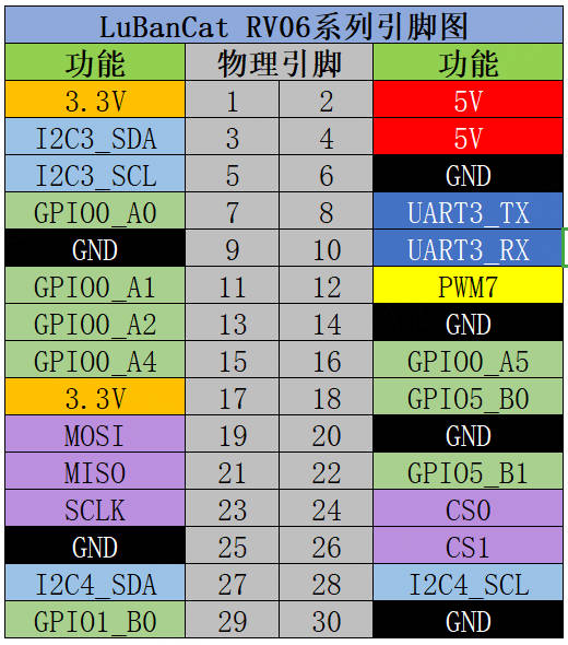
SPI |
引脚 |
功能 |
|---|---|---|
MOSI |
19 |
主设备输出/从设备输入 |
MISO |
21 |
主设备输入/从设备输出 |
CLOCK |
23 |
时钟信号线 |
CS0 |
24 |
片选信号线0 |
CS1 |
26 |
片选信号线1 |
4.1. 检查SPI设备
1 2 3 | # ls /dev/spidev*
/dev/spidev1.0 /dev/spidev1.1
#
|
可以看到出现了两个SPI设备,分别是spidev1.0和spidev1.1,spidev1.0和spidev1.1的区别在于片选信号的不同,spidev1.0使用CS0 , spidev1.1使用CS1
4.2. 回环测试程序
根据ioctl相关参数即可编写spi相关测试程序,此处为了简单仅做回环测试实验, 只需要将SPI3的 MIOS与MOSI引脚(板卡上的19和21)使用跳线帽短接即可。
代码较长复制粘贴容易乱序,可以下载我们提供的源码 spi_selftest.c
quick_start/spi/spi_selftest.c
1 2 3 4 5 6 7 8 9 10 11 12 13 14 15 16 17 18 19 20 21 22 23 24 25 26 27 28 29 30 31 32 33 34 35 36 37 38 39 40 41 42 43 44 45 46 47 48 49 50 51 52 53 54 55 56 57 58 59 60 61 62 63 64 65 66 67 68 69 70 71 72 73 74 75 76 77 78 79 80 81 82 83 84 85 86 87 88 89 90 91 92 93 94 95 96 | #include <sys/ioctl.h>
#include <sys/types.h>
#include <sys/stat.h>
#include <fcntl.h>
#include <unistd.h>
#include <stdio.h>
#include <stdlib.h>
#include <stdint.h>
#include <linux/spi/spidev.h>
/*SPI 接收 、发送 缓冲区*/
unsigned char tx_buffer[100] = "hello the world !";
unsigned char rx_buffer[100];
int fd; // SPI 控制引脚的设备文件描述符
static unsigned mode = SPI_MODE_2; //用于保存 SPI 工作模式
static uint8_t bits = 8; // 接收、发送数据位数
static uint32_t speed = 10000000; // 发送速度
static uint16_t delay; //保存延时时间
void transfer(int fd, uint8_t const *tx, uint8_t const *rx, size_t len)
{
int ret;
struct spi_ioc_transfer tr = {
.tx_buf = (unsigned long)tx,
.rx_buf = (unsigned long)rx,
.len = len,
.delay_usecs = delay,
.speed_hz = speed,
.bits_per_word = bits,
.tx_nbits = 1,
.rx_nbits = 1
};
ret = ioctl(fd, SPI_IOC_MESSAGE(1), &tr);
if (ret < 1)
printf("can't send spi message\n");
}
void spi_init(int fd)
{
int ret = 0;
// spi mode 设置SPI 工作模式
ret = ioctl(fd, SPI_IOC_WR_MODE32, &mode);
if (ret == -1)
printf("can't set spi mode\n");
// bits per word 设置一个字节的位数
ret = ioctl(fd, SPI_IOC_WR_BITS_PER_WORD, &bits);
if (ret == -1)
printf("can't set bits per word\n");
// max speed hz 设置SPI 最高工作频率
ret = ioctl(fd, SPI_IOC_WR_MAX_SPEED_HZ, &speed);
if (ret == -1)
printf("can't set max speed hz\n");
// 打印
printf("spi mode: 0x%x\n", mode);
printf("bits per word: %d\n", bits);
printf("max speed: %d Hz (%d KHz)\n", speed, speed / 1000);
}
int main(int argc, char *argv[])
{
int fd;
if(argc < 2){
printf("Wrong use !!!!\n");
printf("Usage: %s [dev]\n",argv[0]);
return -1;
}
/*打开 SPI 设备*/
fd = open(argv[1], O_RDWR); // open file and enable read and write
if (fd < 0){
printf("Can't open %s \n",argv[1]); // open i2c dev file fail
exit(1);
}
/*初始化SPI */
spi_init(fd);
/*执行发送*/
transfer(fd, tx_buffer, rx_buffer, sizeof(tx_buffer));
/*打印 tx_buffer 和 rx_buffer*/
printf("tx_buffer: \n %s\n ", tx_buffer);
printf("rx_buffer: \n %s\n ", rx_buffer);
close(fd);
return 0;
}
|
4.2.1. 编译运行
将代码放到虚拟机上,然后使用交叉编译工具进行交叉编译,然后将生成的可执行文件发送到板卡上,执行即可。
1 2 3 4 5 6 7 8 | # 交叉编译程序
arm-rockchip830-linux-uclibcgnueabihf-gcc spi_selftest.c -o spi_selftest
# 将生成的可执行文件发送到板卡上
scp spi_selftest root@192.168.103.100:/root
# 执行
./spi_selftest /dev/spidev1.0
|
运行结果如下:
1 2 3 4 5 6 7 8 9 | # ./spi_selftest /dev/spidev1.0
spi mode: 0x2
bits per word: 8
max speed: 10000000 Hz (10000 KHz)
tx_buffer:
hello the world !
rx_buffer:
hello the world !
#
|