
3. I2C通讯
本章简单介绍使用I2C总线与外部设备的通讯,讲解I2C设备的简单使用
3.1. i2c
I2C(Inter-Integrated Circuit)是一种通用的总线协议。它是由Philips(飞利浦)公司, 现NXP(恩智浦)半导体开发的一种简单的双向两线制总线协议标准。
LubanCat-RK系列板卡的 I2C 控制器支持下列功能
兼容 I2C 与 SMBus 总线
仅支持主模式下的 I2C 总线
软件可编程时钟频率支持到 400kbps,最高可达 1000kbps
支持 7 位和 10 位寻址模式
一次中断或轮询至多 32 个字节的数据传输
LubanCat-RV06板卡的30pin接口上有两个I2C接口,分别是I2C-3和I2C-4
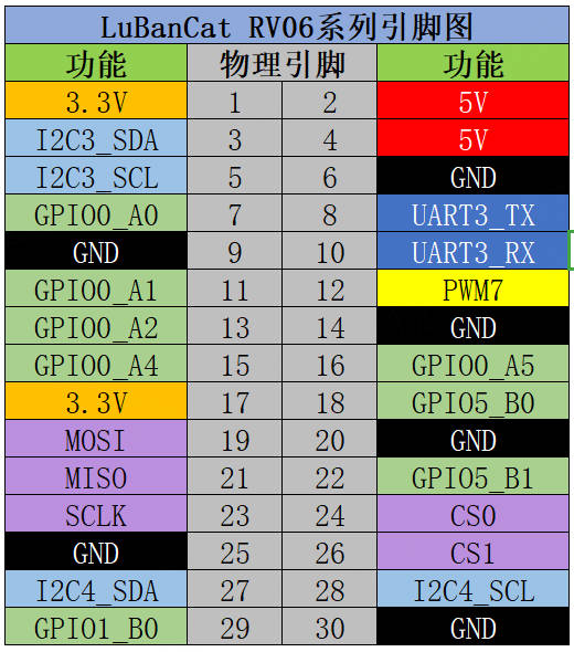
I2C |
引脚 |
功能 |
|---|---|---|
I2C-SCL |
5,28 |
i2c的时钟信号线 |
I2C-SDA |
3,27 |
i2c的数据线 |
3.2. 检查I2C设备
可以通过一下命令查看i2c总线有没有开启
1 | ls /dev/i2c-*
|
如下所示:
1 2 3 | # ls /dev/i2c-*
/dev/i2c-3 /dev/i2c-4
#
|
可以看到出现了两个I2C设备,分别是i2c-3和i2c-4
3.3. 连接设备
将mpu6050接入到i2c-3的总线上,如下图所示
1 2 3 4 5 6 7 | #板卡与mpu6050连接
板子 ------ mpu6050
3.3V(1) ------ VCC
GND(6) ------ GND
SCL(5) ------ SCL
SDA(3) ------ SDA
|
3.4. i2c-tools测试
LubanCat-RV06板卡自带i2c-tools
使用i2c-tools工具包提供了一些非常方便的工具来对系统的I2C总线进行调试, 安装后可使用的命令有i2cdetect、i2cdump、i2cset以及i2cget,用于扫描I2C总线上的设备、读写指定设备的寄存器等。
然后查看挂载在i2c-3上的器件情况,输出内容如下所示:
1 2 3 4 5 6 7 8 9 10 11 | # i2cdetect -y -a 3
0 1 2 3 4 5 6 7 8 9 a b c d e f
00: -- -- -- -- -- -- -- -- -- -- -- -- -- -- -- --
10: -- -- -- -- -- -- -- -- -- -- -- -- -- -- -- --
20: -- UU -- -- -- -- -- -- -- -- -- -- -- -- -- --
30: -- -- -- -- -- -- -- -- -- -- -- -- -- -- -- --
40: -- -- -- -- -- -- -- -- -- -- -- -- -- -- -- --
50: -- -- -- -- -- -- -- -- -- -- -- -- -- -- -- --
60: -- -- -- -- -- -- -- -- 68 -- -- -- -- -- -- --
70: -- -- -- -- -- -- -- -- -- -- -- -- -- -- -- --
#
|
其中 “68” 是为MPU6050的设备地址,常用的命令还有以下几个。
1 2 3 4 5 6 7 8 9 10 11 12 13 14 | #检测当前系统有几组i2c总线
i2cdetect -l
#查看i2c-0接口上的设备
i2cdetect -a -y 3
#读取指定设备的全部寄存器的值。
i2cdump -f -y 3 0x68
#读取指定IIC设备的某个寄存器的值,如下读取地址为0x68器件中的0x01寄存器值。
i2cget -f -y 3 0x68 0x01
#写入指定IIC设备的某个寄存器的值,如下设置地址为0x68器件中的0x01寄存器值为0x6f;
i2cset -f -y 3 0x68 0x01 0x6f
|
3.5. 读取陀螺仪传感器数据实验
3.5.1. 实验说明
本教程将通过IIC接口读取陀螺仪(MPU6050)的原始数据。 本次实验会以i2c-3做为示例,i2c-4的操作和i2c-3的一样, 当然,如果您没有mpu6050模块,可以通过学习操作mpu6050的方式操作您想要操作的i2c设备 在测试程序中大约每一秒读取并显示一次MPU6050的原始数据
查看IIC设备文件,确保IIC 3接口已经使能
1 2 3 | root@lubancat:~# ls /dev/i2c-*
/dev/i2c-3 /dev/i2c-4
root@lubancat:~#
|
其中“i2c-3”就是MPU6050使用到的 IIC 3接口总线。
3.5.2. ioctl函数
在编写应用程序时需要使用ioctl函数设置i2c相关配置,其函数原型如下
1 2 3 | #include <sys/ioctl.h>
int ioctl(int fd, unsigned long request, ...);
|
其中对于终端request的值常用的有以下几种
I2C_RETRIES |
设置收不到ACK时的重试次数,默认为1 |
I2C_TIMEOUT |
设置超时时限的jiffies |
I2C_SLAVE |
设置从机地址 |
I2C_SLAVE_FORCE |
强制设置从机地址 |
I2C_TENBIT |
选择地址长度0为7位地址,非0为10位 |
3.5.3. 编写应用程序
根据ioctl相关参数即可编写与i2c相关的接口函数,读取mpu6050原始数据程序如下
代码较长复制粘贴容易乱序,可以下载我们提供的源码 i2c_mpu6050.c
1 2 3 4 5 6 7 8 9 10 11 12 13 14 15 16 17 18 19 20 21 22 23 24 25 26 27 28 29 30 31 32 33 34 35 36 37 38 39 40 41 42 43 44 45 46 47 48 49 50 51 52 53 54 55 56 57 58 59 60 61 62 63 64 65 66 67 68 69 70 71 72 73 74 75 76 77 78 79 80 81 82 83 84 85 86 87 88 89 90 91 92 93 94 95 96 97 98 99 100 101 102 103 104 105 106 107 108 109 110 111 112 113 114 115 116 117 118 119 120 121 122 123 124 125 126 127 128 129 130 131 132 133 134 135 136 137 138 139 140 141 142 143 144 145 146 147 148 149 150 151 152 153 154 155 | #include <stdio.h>
#include <stdlib.h>
#include <stdint.h>
#include <unistd.h>
#include <sys/types.h>
#include <sys/stat.h>
#include <fcntl.h>
#include <linux/i2c.h>
#include <linux/i2c-dev.h>
#include <sys/ioctl.h>
/*寄存器地址*/
#define SMPLRT_DIV 0x19
#define PWR_MGMT_1 0x6B
#define CONFIG 0x1A
#define ACCEL_CONFIG 0x1C
#define ACCEL_XOUT_H 0x3B
#define ACCEL_XOUT_L 0x3C
#define ACCEL_YOUT_H 0x3D
#define ACCEL_YOUT_L 0x3E
#define ACCEL_ZOUT_H 0x3F
#define ACCEL_ZOUT_L 0x40
#define GYRO_XOUT_H 0x43
#define GYRO_XOUT_L 0x44
#define GYRO_YOUT_H 0x45
#define GYRO_YOUT_L 0x46
#define GYRO_ZOUT_H 0x47
#define GYRO_ZOUT_L 0x48
//从机地址 MPU6050地址
#define Address 0x68
//MPU6050操作相关函数
static int mpu6050_init(int fd,uint8_t addr);
static int i2c_write(int fd, uint8_t addr,uint8_t reg,uint8_t val);
static int i2c_read(int fd, uint8_t addr,uint8_t reg,uint8_t * val);
static short GetData(int fd,uint8_t addr,unsigned char REG_Address);
int main(int argc,char *argv[] )
{
int fd;
fd = I2C_SLAVE;
if(argc < 2){
printf("Wrong use !!!!\n");
printf("Usage: %s [dev]\n",argv[0]);
return -1;
}
fd = open(argv[1], O_RDWR); // open file and enable read and write
if (fd < 0){
perror("Can't open\n"); // open i2c dev file fail
exit(1);
}
//初始化MPU6050
mpu6050_init(fd,Address);
while(1){
usleep(1000 * 10);
printf("ACCE_X:%6d\n ", GetData(fd,Address,ACCEL_XOUT_H));
usleep(1000 * 10);
printf("ACCE_Y:%6d\n ", GetData(fd,Address,ACCEL_YOUT_H));
usleep(1000 * 10);
printf("ACCE_Z:%6d\n ", GetData(fd,Address,ACCEL_ZOUT_H));
usleep(1000 * 10);
printf("GYRO_X:%6d\n ", GetData(fd,Address,GYRO_XOUT_H));
usleep(1000 * 10);
printf("GYRO_Y:%6d\n ", GetData(fd,Address,GYRO_YOUT_H));
usleep(1000 * 10);
printf("GYRO_Z:%6d\n\n ", GetData(fd,Address,GYRO_ZOUT_H));
sleep(1);
}
close(fd);
return 0;
}
static int mpu6050_init(int fd,uint8_t addr)
{
i2c_write(fd, addr,PWR_MGMT_1,0x00); //配置电源管理,0x00,正常启动
i2c_write(fd, addr,SMPLRT_DIV,0x07); //设置MPU6050的输出分频既设置采样
i2c_write(fd, addr,CONFIG,0x06); //配置数字低通滤波器和帧同步引脚
i2c_write(fd, addr,ACCEL_CONFIG,0x01); //设置量程和 X、Y、Z 轴加速度自检
return 0;
}
static int i2c_write(int fd, uint8_t addr,uint8_t reg,uint8_t val)
{
int retries;
uint8_t data[2];
data[0] = reg;
data[1] = val;
//设置地址长度:0为7位地址
ioctl(fd,I2C_TENBIT,0);
//设置从机地址
if (ioctl(fd,I2C_SLAVE,addr) < 0){
printf("fail to set i2c device slave address!\n");
close(fd);
return -1;
}
//设置收不到ACK时的重试次数
ioctl(fd,I2C_RETRIES,5);
if (write(fd, data, 2) == 2){
return 0;
}
else{
return -1;
}
}
static int i2c_read(int fd, uint8_t addr,uint8_t reg,uint8_t * val)
{
int retries;
//设置地址长度:0为7位地址
ioctl(fd,I2C_TENBIT,0);
//设置从机地址
if (ioctl(fd,I2C_SLAVE,addr) < 0){
printf("fail to set i2c device slave address!\n");
close(fd);
return -1;
}
//设置收不到ACK时的重试次数
ioctl(fd,I2C_RETRIES,5);
if (write(fd, ®, 1) == 1){
if (read(fd, val, 1) == 1){
return 0;
}
}
else{
return -1;
}
}
static short GetData(int fd,uint8_t addr,unsigned char REG_Address)
{
char H, L;
i2c_read(fd, addr,REG_Address, &H);
usleep(1000);
i2c_read(fd, addr,REG_Address + 1, &L);
return (H << 8) +L;
}
|
将代码放到虚拟机上,然后使用交叉编译工具进行交叉编译,然后将生成的可执行文件发送到板卡上,执行即可。
1 2 3 4 5 6 7 | # 交叉编译程序
arm-rockchip830-linux-uclibcgnueabihf-gcc i2c_mpu6050.c -o mpu6050
# 将生成的可执行文件发送到板卡上
scp mpu6050 root@192.168.103.100:/root
./mpu6050 /dev/i2c-3
|
三次数据的采集如下所示
1 2 3 4 5 6 7 8 9 10 11 12 13 14 15 16 17 18 19 20 21 | # ./mpu6050 /dev/i2c-3
ACCE_X: 5384
ACCE_Y: -8954
ACCE_Z: 9190
GYRO_X: -2002
GYRO_Y: 4846
GYRO_Z: -1821
ACCE_X: -7798
ACCE_Y:-14158
ACCE_Z: -2296
GYRO_X:-32768
GYRO_Y: 21344
GYRO_Z: 32767
ACCE_X:-21530
ACCE_Y: 12048
ACCE_Z:-22990
GYRO_X: 32767
GYRO_Y:-19531
GYRO_Z:-32768
|