
6. I2C子系统
I2C(Inter-Integrated Circuit)是一种同步、半双工的通信总线该总线经常在嵌入式系统中,用于连接串行EEPROM、RTC芯片、GPIO扩展器、温度传感器等, 本章我们以驱动MPU6050为例讲解i2c驱动程序的编写,本章主要分为五部分内容。
第一部分,i2c基本知识,回忆i2c物理总线和基本通信协议。
第二部分,linux下的i2c驱动框架。
第三部分,i2c总线驱动代码拆解。
第四部分,i2c设备驱动的核心函数。
第五部分,MPU6050驱动以及测试程序。
本章配套源码位于:linux_driver/i2c_mpu6050
6.1. i2c基本知识
6.1.1. i2c物理总线
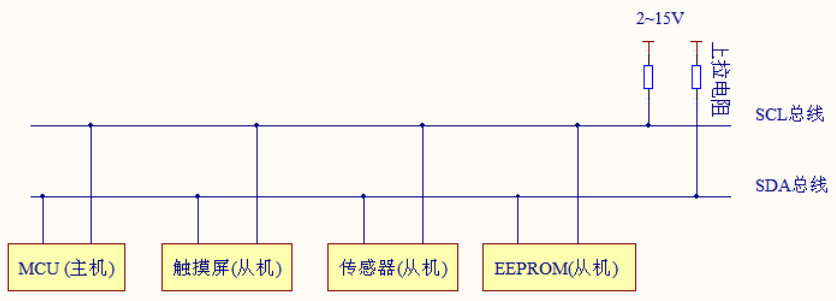
如上图所示,i2c支持一主多从,各设备地址独立,标准模式传输速率为100kbit/s,快速模式为400kbit/s。总线通过上拉电阻接到电源。 当 I2C 设备空闲时,会输出高阻态,而当所有设备都空闲,都输出高阻态时,由上拉电阻把总线拉成高电平。
I2C物理总线使用两条总线线路,SCL和SDA。
SCL: 时钟线,数据收发同步
SDA: 数据线,传输具体数据
6.1.2. i2c基本通信协议
6.1.2.1. 起始信号(S)与停止信号(P)
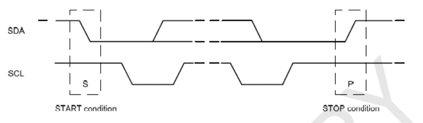
当SCL线为高电平时,SDA线由高到低的下降沿,为传输开始标志(S)。直到主设备发出结束信号(P), 否则总线状态一直为忙。结束标志(P)为,当SCL线为高电平时,SDA线由低到高的上升沿。
6.1.2.2. 数据格式与应答信号(ACK/NACK)
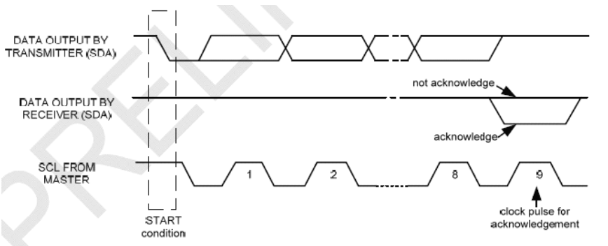
i2c的数据字节定义为8-bits长度,对每次传送的总字节数量没有限制,但对每一次传输必须伴有一个应答(ACK)信号, 其时钟由主设备提供,而真正的应答信号由从设备发出,在时钟为高时,通过拉低并保持SDA的值来实现。如果从设备忙, 它可以使 SCL保持在低电平,这会强制使主设备进入等待状态。当从设备空闲后,并且释放时钟线,原来的数据传输才会继续。
6.1.2.3. 主机与从机通信
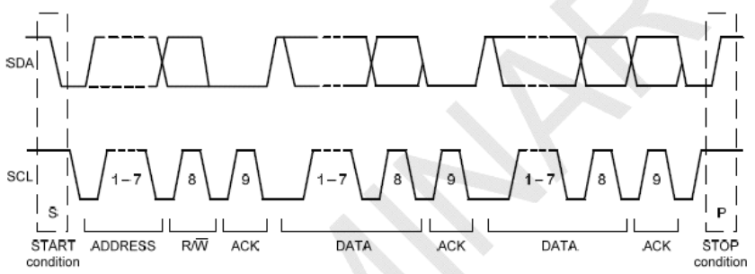
开始标志(S)发出后,主设备会传送一个7位的Slave地址,并且后面跟着一个第8位,称为Read/Write位。 R/W位表示主设备是在接受从设备的数据还是在向其写数据。然后,主设备释放SDA线,等待从设备的应答信号(ACK)。 每个字节的传输都要跟随有一个应答位。应答产生时,从设备将SDA线拉低并且在SCL为高电平时保持低。 数据传输总是以停止标志(P)结束,然后释放通信线路。 然而,主设备也可以产生重复的开始信号去操作另一台从设备, 而不发出结束标志。综上可知,所有的SDA信号变化都要在SCL时钟为低电平时进行,除了开始和结束标志
6.1.2.4. i2c对mpu6050进行数据读写
单字节写入
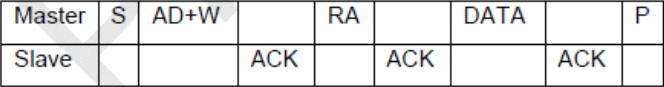
连续字节写入
对MPU6050进行写操作时,主设备发出开始标志(S)和写地址(地址位加一个R/W位,0为写)。 MPU6050产生应答信号。然后主设备开始传送寄存器地址(RA),接到应答后,开始传送寄存器数据, 然后仍然要有应答信号,连续写入多字节时依次类推。
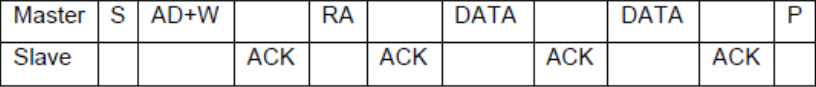
单字节读出

连续字节读出

对MPU6050进行读操作时,主设备发出开始标志(S)和读地址(地址位加一个R/W位,1为读)。 等待MPU6050产生应答信号。然后发送寄存器地址,告诉MPU6050读哪一个寄存器。 紧接着,收到应答信号后,主设备再发一个开始信号,然后发送从设备读地址。 MPU6050产生应答信号并开始发送寄存器数据。通信以主设备产生的拒绝应答信号(NACK)和结束标志(P)结束。
学过单片机的用户对i2c协议并不陌生,这里只是简单的讲解,如果忘记可参考 【野火®】零死角玩转STM32 中i2c章节。
6.2. i2c驱动框架
在编写单片机裸机i2c驱动时我们需要根据i2c协议手动配置i2c控制寄存器使其能够输出起始信号、停止信号、数据信息等等。
在Linux系统中则采用了总线、设备驱动模型。我们之前讲解的平台设备也是采用了这种模型,只不过平台总线是一个虚拟的总线。
我们知道一个i2c(例如i2c1)上可以挂在多个i2c设备,例如MPU6050、i2c接口的OLED显示屏、摄像头(摄像头通过i2c接口发送控制信息)等等, 这些设备共用一个i2c,这个i2c的驱动我们称为i2c总线驱动。而对应具体的设备,例如mpu6050的驱动就是i2c设备驱动。 这样我们要使用mpu6050就需要拥有“两个驱动”一个是i2c总线驱动和mpu6050设备驱动。
i2c总线驱动由芯片厂商提供(驱动复杂,官方提供了经过测试的驱动,我们直接用),
mpu6050设备驱动可以从mpu6050芯片厂家那里获得(不确定有),也可以我们手动编写。
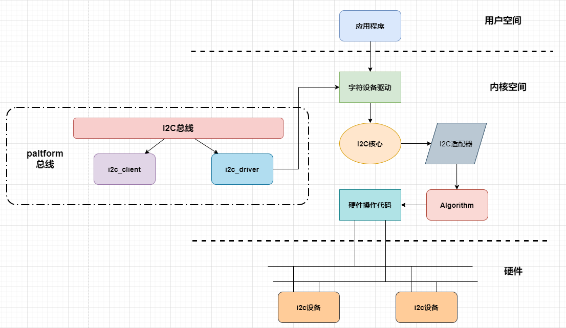
如上图所示,i2c驱动框架包括i2c总线驱动、具体某个设备的驱动。
i2c总线包括i2c设备(i2c_client)和i2c驱动(i2c_driver), 当我们向linux中注册设备或驱动的时候,按照i2c总线匹配规则进行配对,配对成功,则可以通过i2c_driver中.prob函数创建具体的设备驱动。 在现代linux中,i2c设备不再需要手动创建,而是使用设备树机制引入,设备树节点是与paltform总线相配合使用的。 所以需先对i2c总线包装一层paltform总线,当设备树节点转换为平台总线设备时,我们在进一步将其转换为i2c设备,注册到i2c总线中。
设备驱动创建成功,我们还需要实现设备的文件操作接口(file_operations),file_operations中会使用到内核中i2c核心函数(i2c系统已经实现的函数,专门开放给驱动工程师使用)。 使用这些函数会涉及到i2c适配器,也就是i2c控制器。由于ic2控制器有不同的配置,所有linux将每一个i2c控制器抽象成i2c适配器对象。 这个对象中存在一个很重要的成员变量——Algorithm,Algorithm中存在一系列函数指针,这些函数指针指向真正硬件操作代码。
6.2.1. 关键数据结构
在开始拆解i2c驱动框架的源码之前,先了解其中几个重要的对象。
struct i2c_adapter
i2c_适配器对应一个i2c控制器,是用于标识物理i2c总线以及访问它所需的访问算法的结构。
1 2 3 4 5 6 7 8 9 10 11 12 13 14 15 16 17 18 19 20 21 22 23 24 25 26 27 | /*
* i2c_adapter is the structure used to identify a physical i2c bus along
* with the access algorithms necessary to access it.
*/
struct i2c_adapter {
struct module *owner;
unsigned int class; /* classes to allow probing for */
const struct i2c_algorithm *algo; /* the algorithm to access the bus */
void *algo_data;
/* data fields that are valid for all devices */
struct rt_mutex bus_lock;
int timeout; /* in jiffies */
int retries;
struct device dev; /* the adapter device */
int nr;
char name[48];
struct completion dev_released;
struct mutex userspace_clients_lock;
struct list_head userspace_clients;
struct i2c_bus_recovery_info *bus_recovery_info;
const struct i2c_adapter_quirks *quirks;
};
|
algo: struct i2c_algorithm 结构体,访问总线的算法;
dev: struct device 结构体,控制器,表明这是一个设备。
struct i2c_algorithm
i2c_algorithm是对i2c通信方法的抽象接口,这个抽象接口使得不同芯片上的i2c外设,能使用i2c总线模型。
struct i2c_algorithm结构体用于指定访问总线(i2c)的算法, 结构体中包含了几个函数指针成员,不同的厂商根据自身硬件的特性,来自行实现自己的i2c传输功能。
更直白的说,i2c设备例如mpu6050、i2c接口的oled屏等等,就会通过这些函数接口使用i2c总线实现收、发数据的。 在i2c的总线驱动中会实现这些(部分)函数。
1 2 3 4 5 6 7 8 9 10 11 12 13 14 15 16 17 18 19 20 21 | struct i2c_algorithm {
/* If an adapter algorithm can't do I2C-level access, set master_xfer
to NULL. If an adapter algorithm can do SMBus access, set
smbus_xfer. If set to NULL, the SMBus protocol is simulated
using common I2C messages */
/* master_xfer should return the number of messages successfully
processed, or a negative value on error */
int (*master_xfer)(struct i2c_adapter *adap, struct i2c_msg *msgs,
int num);
int (*smbus_xfer) (struct i2c_adapter *adap, u16 addr,
unsigned short flags, char read_write,
u8 command, int size, union i2c_smbus_data *data);
/* To determine what the adapter supports */
u32 (*functionality) (struct i2c_adapter *);
#if IS_ENABLED(CONFIG_I2C_SLAVE)
int (*reg_slave)(struct i2c_client *client);
int (*unreg_slave)(struct i2c_client *client);
#endif
};
|
master_xfer: 作为主设备时的发送函数,应该返回成功处理的消息数,或者在出错时返回负值。
smbus_xfer: smbus是一种i2c协议的协议,如硬件上支持,可以实现这个接口。
struct i2c_client
表示i2c从设备
1 2 3 4 5 6 7 8 9 10 11 12 13 14 | struct i2c_client {
unsigned short flags; /* div., see below */
unsigned short addr; /* chip address - NOTE: 7bit */
char name[I2C_NAME_SIZE];
struct i2c_adapter *adapter; /* the adapter we sit on */
struct device dev; /* the device structure */
int init_irq; /* irq set at initialization */
int irq; /* irq issued by device */
struct list_head detected;
#if IS_ENABLED(CONFIG_I2C_SLAVE)
i2c_slave_cb_t slave_cb; /* callback for slave mode */
#endif
};
|
flags: :I2C_CLIENT_TEN表示设备使用10位芯片地址,I2C客户端PEC表示它使用SMBus数据包错误检查
addr: addr在连接到父适配器的I2C总线上使用的地址。
name: 表示设备的类型,通常是芯片名。
adapter: struct i2c_adapter 结构体,管理托管这个I2C设备的总线段。
dev: Driver model设备节点。
init_irq: 作为从设备时的发送函数。
irq: 表示该设备生成的中断号。
detected: struct list_head i2c的成员_驱动程序.客户端列表或i2c核心的用户空间设备列表。
slave_cb: 使用适配器的I2C从模式时回调。适配器调用它来将从属事件传递给从属驱动程序。i2c_客户端识别连接到i2c总线的单个设备(即芯片)。暴露在Linux下的行为是由管理设备的驱动程序定义的。
struct i2c_driver
i2c设备驱动程序
1 2 3 4 5 6 7 8 9 10 11 12 13 14 15 16 | struct i2c_driver {
unsigned int class;
int (*probe)(struct i2c_client *, const struct i2c_device_id *);
int (*remove)(struct i2c_client *);
struct device_driver driver;
const struct i2c_device_id *id_table;
int (*detect)(struct i2c_client *, struct i2c_board_info *);
const unsigned short *address_list;
struct list_head clients;
...
};
|
probe: i2c设备和i2c驱动匹配后,回调该函数指针。
id_table: struct i2c_device_id 要匹配的从设备信息。
address_list: 设备地址
clients: 设备链表
detect: 设备探测函数
6.3. i2c总线驱动
i2c总线驱动由芯片厂商提供,如果我们使用全志官方提供的Linux内核,i2c总线驱动已经保存在内核中,并且默认情况下已经编译进内核。
下面结合源码简单介绍i2c总线的运行机制。
1、注册I2C总线
2、将I2C驱动添加到I2C总线的驱动链表中
3、遍历I2C总线上的设备链表,根据i2c_device_match函数进行匹配,如果匹配调用i2c_device_probe函数
4、i2c_device_probe函数会调用I2C驱动的probe函数
i2c总线定义
1 2 3 4 5 6 7 | struct bus_type i2c_bus_type = {
.name = "i2c",
.match = i2c_device_match,
.probe = i2c_device_probe,
.remove = i2c_device_remove,
.shutdown = i2c_device_shutdown,
};
|
i2c总线维护着两个链表(I2C驱动、I2C设备),管理I2C设备和I2C驱动的匹配和删除等
i2c总线注册
linux启动之后,默认执行i2c_init。
1 2 3 4 5 6 7 8 9 10 11 12 13 14 15 16 17 18 19 20 21 22 | static int __init i2c_init(void)
{
int retval;
...
retval = bus_register(&i2c_bus_type);
if (retval)
return retval;
is_registered = true;
...
retval = i2c_add_driver(&dummy_driver);
if (retval)
goto class_err;
if (IS_ENABLED(CONFIG_OF_DYNAMIC))
WARN_ON(of_reconfig_notifier_register(&i2c_of_notifier));
if (IS_ENABLED(CONFIG_ACPI))
WARN_ON(acpi_reconfig_notifier_register(&i2c_acpi_notifier));
return 0;
...
}
|
第5行:bus_register注册总线i2c_bus_type,总线定义如上所示。
第11行:i2c_add_driver注册设备dummy_driver。
i2c设备和i2c驱动匹配规则
1 2 3 4 5 6 7 8 9 10 11 12 13 14 15 16 17 18 19 20 21 | static int i2c_device_match(struct device *dev, struct device_driver *drv)
{
struct i2c_client *client = i2c_verify_client(dev);
struct i2c_driver *driver;
/* Attempt an OF style match */
if (i2c_of_match_device(drv->of_match_table, client))
return 1;
/* Then ACPI style match */
if (acpi_driver_match_device(dev, drv))
return 1;
driver = to_i2c_driver(drv);
/* Finally an I2C match */
if (i2c_match_id(driver->id_table, client))
return 1;
return 0;
}
|
of_driver_match_device: 设备树匹配方式,比较 I2C 设备节点的 compatible 属性和 of_device_id 中的 compatible 属性
acpi_driver_match_device: ACPI 匹配方式
i2c_match_id: i2c总线传统匹配方式,比较 I2C设备名字和 i2c驱动的id_table->name 字段是否相等
在i2c总线驱动代码源文件中,我们只简单介绍重要的几个点,如果感兴趣可自行阅读完整的i2c驱动源码。 通常情况下,看驱动程序首先要找到驱动的入口和出口函数,驱动入口和出口位于驱动的末尾,如下所示:
1 2 3 4 5 6 7 8 9 10 11 | static struct platform_driver sunxi_i2c_driver = {
.probe = sunxi_i2c_probe,
.remove = sunxi_i2c_remove,
.shutdown = sunxi_i2c_shutdown,
.driver = {
.name = SUNXI_I2C_DEV_NAME,
.owner = THIS_MODULE,
.pm = SUNXI_I2C_DEV_PM_OPS,
.of_match_table = sunxi_i2c_match,
},
};
|
驱动注册函数module_platform_driver(定义在内核源码/include/linux/platform_device.h),该宏详细请参考前面动态设备树章节, 我们可以从中得到i2c驱动是一个平台驱动,并且我们知道平台驱动结构体是“sunxi_i2c_driver”,平台驱动结构体如下所示。
1 2 3 4 5 6 7 8 9 10 11 12 13 14 15 16 17 18 19 | static const struct of_device_id sunxi_i2c_match[] = {
{ .compatible = "allwinner,sun8i-twi", },
{ .compatible = "allwinner,sun20i-twi", },
{ .compatible = "allwinner,sun50i-twi", },
{},
};
MODULE_DEVICE_TABLE(of, sunxi_i2c_match);
static struct platform_driver sunxi_i2c_driver = {
    .probe          = sunxi_i2c_probe,
    .remove         = sunxi_i2c_remove,
    .shutdown       = sunxi_i2c_shutdown,
    .driver         = {
        .name       = SUNXI_I2C_DEV_NAME,
        .owner      = THIS_MODULE,
        .pm         = SUNXI_I2C_DEV_PM_OPS,
        .of_match_table = sunxi_i2c_match,
    },
};
|
第1-5行:是i2c驱动的匹配表,用于和设备树节点匹配,
第9-19行:是初始化的平台设备结构体,从这个结构体我们可以找到.prob函数,.prob函数的作用我们都很清楚,通常情况下该函数实现设备的基本初始化。
以下是.porbe函数的内容。
1 2 3 4 5 6 7 8 9 10 11 12 13 14 15 16 17 18 19 20 21 22 23 24 25 26 27 28 29 30 31 32 33 34 35 36 37 38 39 40 41 42 43 44 45 46 47 48 49 50 51 52 53 54 55 56 57 58 59 60 61 62 63 64 65 66 67 68 69 70 71 72 73 74 75 76 77 78 79 80 81 82 83 84 85 86 | static int sunxi_i2c_probe(struct platform_device *pdev)
{
struct sunxi_i2c *i2c = NULL;
int err;
i2c = devm_kzalloc(&pdev->dev, sizeof(struct sunxi_i2c), GFP_KERNEL);
if (!i2c) {
dev_err(i2c->dev, "I2C failed to kzlloc sunxi_i2c struct\n");
return -ENOMEM;
}
i2c->pdev = pdev;
i2c->dev = &pdev->dev;
pdev->name = dev_name(i2c->dev);
/* get dts resource */
err = sunxi_i2c_resource_get(pdev->dev.of_node, i2c);
if (err) {
dev_err(i2c->dev, "I2C failed to get resource\n");
goto err0;
}
/* i2c controller hardware init */
err = sunxi_i2c_hw_init(i2c);
if (err) {
dev_err(i2c->dev, "hw init failed! try again!!\n");
goto err1;
}
spin_lock_init(&i2c->lock);
init_waitqueue_head(&i2c->wait);
sunxi_i2c_create_sysfs(pdev);
pm_runtime_set_active(i2c->dev);
if (i2c->no_suspend)
pm_runtime_get_noresume(i2c->dev);
pm_runtime_set_autosuspend_delay(i2c->dev, AUTOSUSPEND_TIMEOUT);
pm_runtime_use_autosuspend(i2c->dev);
pm_runtime_enable(i2c->dev);
snprintf(i2c->adap.name, sizeof(i2c->adap.name), dev_name(&pdev->dev));
i2c->status = I2C_XFER_IDLE;
i2c->adap.owner = THIS_MODULE;
i2c->adap.nr = i2c->bus_num;
i2c->adap.retries = 3;
i2c->adap.timeout = 5*HZ;
i2c->adap.class = I2C_CLASS_HWMON | I2C_CLASS_SPD;
i2c->adap.algo = &sunxi_i2c_algorithm;
i2c->adap.bus_recovery_info = &sunxi_i2c_bus_recovery;
i2c->adap.algo_data = i2c;
i2c->adap.dev.parent = &pdev->dev;
i2c->adap.dev.of_node = pdev->dev.of_node;
platform_set_drvdata(pdev, i2c);
/*
* register i2c adapter should be the ending of probe
* before register all the resouce i2c controller need be ready
* (i2c_xfer may occur at any time when register)
*/
err = i2c_add_numbered_adapter(&i2c->adap);
if (err) {
dev_err(i2c->dev, "failed to add adapter\n");
goto err2;
}
if (!i2c->no_suspend) {
pm_runtime_mark_last_busy(i2c->dev);
pm_runtime_put_autosuspend(i2c->dev);
}
dev_info(i2c->dev, "probe success\n");
return 0;
err2:
pm_runtime_set_suspended(i2c->dev);
pm_runtime_disable(i2c->dev);
sunxi_i2c_remove_sysfs(pdev);
sunxi_i2c_hw_exit(i2c);
err1:
sunxi_i2c_resource_put(i2c);
err0:
return err;
}
|
第6-10行:为sunxi_i2c结构体分配内存。devm_kzalloc是设备资源管理的内存分配函数,自动释放内存。GFP_KERNEL是内存分配标志,表示在内核空间分配内存。
第12-14行:初始化sunxi_i2c结构体的成员。pdev是平台设备指针,保存到i2c->pdev,i2c->dev指向平台设备的设备结构体,pdev->name设置为设备名称。
第17-21行:从设备树中获取I2C控制器的资源,如寄存器地址、中断号等。
第24-28行:初始化I2C控制器的硬件,如配置寄存器、时钟等。
第30-31行:初始化自旋锁和等待队列。
第33行:在/sys文件系统中创建接口,用于用户空间与驱动交互。
第35-40行:初始化运行时电源管理。
第42-54行:初始化I2C适配器结构体,platform_set_drvdata将i2c结构体绑定到平台设备。
第61-65行:将I2C适配器注册到内核。
第67-70行:标记设备为“最近使用”并释放电源管理引用。
第75-85行:在发生错误时释放资源,err2释放电源管理、移除 sysfs 接口、关闭硬件,err1释放设备树资源,err0返回错误码。
下面我们来看看sunxi_i2c结构体,它是切实用于产商芯片和linux平台关联的桥梁。
1 2 3 4 5 6 7 8 9 10 11 12 13 14 15 16 17 18 19 20 21 22 23 24 25 26 27 28 29 30 31 32 33 34 35 36 37 38 39 40 41 42 43 44 | struct sunxi_i2c {
/* i2c framework datai */
struct i2c_adapter adap;
struct platform_device *pdev;
struct device *dev;
struct i2c_msg *msg;
/* the total num of msg */
unsigned int msg_num;
/* the current msg index -> msg[msg_idx] */
unsigned int msg_idx;
/* the current msg's buf data index -> msg->buf[buf_idx] */
unsigned int buf_idx;
unsigned int result;
/* dts data */
struct resource *res;
void __iomem *base_addr;
struct clk *bus_clk;
struct reset_control *reset;
unsigned int bus_freq;
struct regulator *regulator;
struct pinctrl *pctrl;
int irq;
int irq_flag;
unsigned int twi_drv_used;
unsigned int no_suspend;
unsigned int pkt_interval;
struct sunxi_i2c_dma *dma_tx;
struct sunxi_i2c_dma *dma_rx;
struct sunxi_i2c_dma *dma_using;
u8 *dma_buf;
/* other data */
int bus_num;
unsigned int status; /* start, running, idle */
unsigned int debug_state; /* log the twi machine state */
spinlock_t lock; /* syn */
wait_queue_head_t wait;
struct completion cmd_complete;
unsigned int reg1[16]; /* store the i2c engined mode resigter status */
unsigned int reg2[16]; /* store the i2c drv mode regiter status */
};
|
sunxi_i2c结构体成员较多,描述了厂商的i2c控制器信息以及即将注册到总线中的adapter适配器, 通过这个结构体,可以关联linux下的i2c总线模型和产商芯片驱动功能。
adap: 即将注册到总线中的adapter适配器
irq: 保存i2c的中断号
clk: clk结构体保存时钟相关信息
busy: 事件等待的条件
在前面的probe函数函数中,初始化sunxi_i2c结构体中的adap成员。
我们重点看49行的:“i2c->adap.algo = &sunxi_i2c_algorithm;”, 它就是用于初始化“访问i2c总线的传输算法”。“sunxi_i2c_algorithm”定义如下。
1 2 3 4 | static const struct i2c_algorithm sunxi_i2c_algorithm = {
.master_xfer = sunxi_i2c_xfer,
.functionality = sunxi_i2c_functionality,
};
|
sunxi_i2c_algorithm结构体内指定了两个函数,它们就是外部访问i2c总线的接口:
函数sunxi_i2c_functionality只是用于返回I2C总线提供的功能。
函数sunxi_i2c_xfer真正实现访问i2c外设,进行数据传输。
sunxi_i2c_xfer函数定义如下:
1 2 3 4 5 6 7 8 9 10 11 12 13 14 15 16 17 18 19 20 21 22 23 24 25 26 27 28 29 30 31 32 33 34 35 36 37 38 | static int
sunxi_i2c_xfer(struct i2c_adapter *adap, struct i2c_msg *msgs, int num)
{
struct sunxi_i2c *i2c = (struct sunxi_i2c *)adap->algo_data;
int ret;
if (IS_ERR_OR_NULL(msgs) || (num <= 0)) {
dev_err(i2c->dev, "invalid argument\n");
return -EINVAL;
}
/* then the sunxi_i2c_runtime_reseme() call back */
ret = pm_runtime_get_sync(i2c->dev);
if (ret < 0)
goto out;
sunxi_i2c_soft_reset(i2c);
ret = sunxi_i2c_bus_barrier(&i2c->adap);
if (ret) {
dev_err(i2c->dev, "i2c bus barrier failed, sda is still low!\n");
goto out;
}
/* set the i2c status to idle */
i2c->result = RESULT_IDLE;
if (i2c->twi_drv_used)
ret = sunxi_i2c_drv_xfer(i2c, msgs, num);
else
ret = sunxi_i2c_engine_xfer(i2c, msgs, num);
out:
pm_runtime_mark_last_busy(i2c->dev);
/* asnyc release to ensure other module all suspend */
pm_runtime_put_autosuspend(i2c->dev);
return ret;
}
|
在编写设备驱动如mpu6050的驱动时,我们会使用“i2c_transfer”函数执行数据的传输,i2c_transfer函数最终就是调用sunxi_i2c_xfer函数实现具体的收发工作。 届时我们会详细介绍i2c_transfer函数的用法。
在sunxi_i2c_xfer中,实际的收发又是通过sunxi_i2c_drv_xfer或者sunxi_i2c_engine_xfer来完成,函数实现如下:
1 2 3 4 5 6 7 8 9 10 11 12 13 14 15 16 17 18 19 20 21 22 23 24 25 26 27 28 29 30 31 32 33 34 35 36 37 38 39 40 41 42 43 44 45 46 47 48 49 50 51 52 53 54 55 56 57 58 59 60 61 62 63 64 65 66 67 68 69 70 71 72 73 74 75 76 77 78 79 | static int
sunxi_i2c_drv_xfer(struct sunxi_i2c *i2c, struct i2c_msg *msgs, int num)
{
int i = 0;
unsigned long flags;
spin_lock_irqsave(&i2c->lock, flags);
i2c->result = RESULT_IDLE;
spin_unlock_irqrestore(&i2c->lock, flags);
sunxi_i2c_drv_clear_irq(i2c->base_addr, I2C_DRV_INT_STA_MASK);
sunxi_i2c_drv_disable_irq(i2c->base_addr, I2C_DRV_INT_STA_MASK);
sunxi_i2c_drv_disable_dma_irq(i2c->base_addr, DMA_TX_EN | DMA_RX_EN);
sunxi_i2c_drv_clear_txfifo(i2c->base_addr);
sunxi_i2c_drv_clear_rxfifo(i2c->base_addr);
while (i < num) {
dev_dbg(i2c->dev, "drv-mode: addr: 0x%x, flag:%x, len:%d\n",
msgs[i].addr, msgs[i].flags, msgs[i].len);
if (msgs[i].flags & I2C_M_RD) {
if (sunxi_i2c_drv_rx_msgs(i2c, &msgs[i], 1))
return -EINVAL;
i++;
} else if (i + 1 < num && msgs[i + 1].flags & I2C_M_RD) {
if (sunxi_i2c_drv_rx_msgs(i2c, &msgs[i], 2))
return -EINVAL;
i += 2;
} else {
if (sunxi_i2c_drv_tx_one_msg(i2c, &msgs[i]))
return -EINVAL;
i++;
}
}
return i;
}
static int
sunxi_i2c_engine_xfer(struct sunxi_i2c *i2c, struct i2c_msg *msgs, int num)
{
unsigned long flags;
int ret;
void __iomem *base_addr = i2c->base_addr;
sunxi_i2c_engine_disable_ack(base_addr);
sunxi_i2c_engine_set_efr(base_addr, NO_DATA_WROTE);
sunxi_i2c_engine_clear_irq(base_addr);
/* may conflict with xfer_complete */
spin_lock_irqsave(&i2c->lock, flags);
i2c->msg = msgs;
i2c->msg_num = num;
i2c->msg_idx = 0;
i2c->result = RESULT_IDLE;
i2c->status = I2C_XFER_START;
spin_unlock_irqrestore(&i2c->lock, flags);
sunxi_i2c_engine_enable_irq(base_addr);
/* then send START signal, and needn't clear int flag */
ret = sunxi_i2c_engine_start(i2c);
if (ret) {
dev_err(i2c->dev, "i2c failed to send start signal\n");
sunxi_i2c_soft_reset(i2c);
sunxi_i2c_engine_disable_irq(i2c->base_addr);
i2c->status = I2C_XFER_IDLE;
return -EINVAL;
}
spin_lock_irqsave(&i2c->lock, flags);
i2c->status = I2C_XFER_RUNNING;
spin_unlock_irqrestore(&i2c->lock, flags);
/*
* sleep and wait, timeput = 5*HZ
* then do the transfer at function : sunxi_i2c_engine_core_process
*/
return sunxi_i2c_engine_complete(i2c);
}
|
sunxi_i2c_drv_xfer:通过直接操作I2C控制器的寄存器完成数据传输,属于纯软件驱动模式。
sunxi_i2c_engine_xfer:利用SoC内置的硬件引擎(如专用DMA控制器)实现高效传输,减少CPU占用。
更多内容就不带大家展开了,操作内容都是比较针对底层外设寄存器的,简单解释参考代码中的注释。
至此我们的i2c平台驱动就给大家分析完了,probe函数完成了i2c的基本初始化并将其添加到了系统中。 驱动中也实现i2c对外接口函数。 我们在初始化i2c_adapter结构体时已经初始化了访问总线算法结构体i2c_algorithm,在前面也介绍过了。
那么总结整个probe函数,主要完成了两个工作。第一,初始化i2c硬件,第二,初始化一个可以访问i2c外设的i2c_adapter结构体,并将其添加到系统中。
6.4. i2c设备驱动核心函数
i2c_add_adapter()
向linux系统注册一个i2c适配器
1 2 3 4 | //linux系统自动设置i2c适配器编号(adapter->nr)
int i2c_add_adapter(struct i2c_adapter *adapter)
//手动设置i2c适配器编号(adapter->nr)
int i2c_add_numbered_adapter(struct i2c_adapter *adapter)
|
参数:
adapter: i2c物理控制器对应的适配器
返回值:
成功: 0
失败: 负数
i2c_add_driver()宏
1 | #define i2c_add_driver(driver)
|
这个宏函数的本质是调用了i2c_register_driver()函数,函数如下。
i2c_register_driver()函数
1 | int i2c_register_driver(struct module *owner, struct i2c_driver *driver)
|
参数:
owner: 一般为 THIS_MODULE
driver: 要注册的 i2c_driver.
返回值:
成功: 0
失败: 负数
i2c_transfer()函数
i2c_transfer()函数最终就是调用我们前面讲到的rk3x_i2c_xfer()函数来实现数据传输。
1 | int i2c_transfer(struct i2c_adapter *adap, struct i2c_msg *msgs, int num)
|
参数:
adap : struct i2c_adapter 结构体,收发消息所使用的i2c适配器,i2c_client 会保存其对应的 i2c_adapter
msgs: struct i2c_msg 结构体,i2c要发送的一个或多个消息
num : 消息数量,也就是msgs的数量
返回值:
成功: 发送的msgs的数量
失败: 负数
i2c_msg结构体
1 2 3 4 5 6 7 | struct i2c_msg {
__u16 addr; /* slave address */
__u16 flags;
...
__u16 len; /* msg length */
__u8 *buf; /* pointer to msg data */
};
|
addr: iic设备地址
flags: 消息传输方向和特性。I2C_M_RD:表示读取消息;0:表示发送消息。
len: 消息数据的长度
buf: 字符数组存放消息,作为消息的缓冲区
i2c_master_send()函数
1 2 3 4 5 | static inline int i2c_master_send(const struct i2c_client *client,
const char *buf, int count)
{
return i2c_transfer_buffer_flags(client, (char *)buf, count, 0);
};
|
i2c_master_recv()函数
1 2 3 4 5 | static inline int i2c_master_recv(const struct i2c_client *client,
char *buf, int count)
{
return i2c_transfer_buffer_flags(client, buf, count, I2C_M_RD);
};
|
i2c_transfer_buffer_flags()函数
1 2 3 4 5 6 7 8 9 10 11 12 13 14 15 16 17 18 19 | int i2c_transfer_buffer_flags(const struct i2c_client *client, char *buf,
int count, u16 flags)
{
int ret;
struct i2c_msg msg = {
.addr = client->addr,
.flags = flags | (client->flags & I2C_M_TEN),
.len = count,
.buf = buf,
};
ret = i2c_transfer(client->adapter, &msg, 1);
/*
* If everything went ok (i.e. 1 msg transferred), return #bytes
* transferred, else error code.
*/
return (ret == 1) ? count : ret;
}
|
下面以mpu6050为例讲解如何编写i2c设备驱动。
6.5. mpu6050驱动实验
6.5.1. 硬件介绍
本节实验使用LubanCat-A1板卡为例,以及 《野火MPU6050模块》 。
MPU6050是一款运动处理传感器,它集成了3轴MEMS陀螺仪,3轴MEMS加速度计。
mpu6050和板卡的引脚连接对应表:
MPU6050引脚(模块丝印) |
说明 |
板卡引脚 |
|---|---|---|
SCL |
SCL引脚 |
I2C4_SCL |
SDA |
SDA引脚 |
I2C4_SDA |
XDA |
没有使用 |
|
XCL |
没有使用 |
|
AD0 |
接地 |
GND |
int |
悬空或者接地 |
|
GND |
GND |
GND |
VCC |
电源 |
3.3V |
提示
请看“LubanCat-RK系列板卡快速使用手册”的pin引脚对照图。
MPU6050是通过i2c连接到开发板的,其中传感器上的SDA和SCL连到开发板i2c4, 开发板要控制MPU6050需要先复用这两个引脚为i2c控制器引脚。
查看MPU芯片手册我们可以知道,MPU6050的slave地址为b110100X,七位字长,最低有效位X由AD0管脚上的逻辑电平决定。 从原理图上可以看到,AD0接地,则地址为b1101000,也就是0x68,另外,中断引脚“int”没有使用。
6.5.2. 实验代码讲解
6.5.2.2. I2C设备树和设备树插件
使用i2c4和mpu6050通信,下面是i2c4控制器的设备树代码:
1 2 3 4 5 6 7 8 9 10 11 12 13 14 | twi4: twi@5003000 {
#address-cells = <1>;
#size-cells = <0>;
compatible = "allwinner,sun50i-twi";
device_type = "twi4";
reg = <0x0 0x05003000 0x0 0x400>;
interrupts = <GIC_SPI 10 IRQ_TYPE_LEVEL_HIGH>;
clocks = <&ccu CLK_BUS_I2C4>;
clock-names = "bus";
resets = <&ccu RST_BUS_I2C4>;
dmas = <&dma 47>, <&dma 47>;
dma-names = "tx", "rx";
status = "disabled";
};
|
定义了twi4控制器的寄存器地址、中断、时钟、复位信号、DMA 通道等硬件信息。
1 2 3 4 5 6 7 8 | &twi4 {
clock-frequency = <400000>;
pinctrl-0 = <&twi4_pins_a>;
pinctrl-1 = <&twi4_pins_b>;
pinctrl-names = "default", "sleep";
twi_drv_used = <0>;
status = "disabled";
};
|
设置I2C总线频率、引脚复用、驱动模式等。
1 2 3 4 5 6 7 8 9 10 11 | twi4_pins_a: twi4@0 {
pins = "PG15", "PG16";
function = "twi4";
drive-strength = <10>;
bias-pull-up;
};
twi4_pins_b: twi4@1 {
pins = "PG15", "PG16";
function = "gpio_in";
};
|
配置引脚复用,确保twi4控制器在正常工作和休眠状态下使用正确的引脚配置。
以上内容是默认配置好了的,因此如果我们需要使用twi4接口,直接将twi4节点打开即可。
本章节使用设备树插件方式,在内核源码/arch/arm64/boot/dts/sunxi/overlay/目录创建h618-lubancat-mpu6050-overlay.dts, 内容如下所示
1 2 3 4 5 6 7 8 9 10 11 12 13 14 15 16 17 18 19 20 | /dts-v1/;
/plugin/;
/ {
fragment@0 {
target = <&twi4>;
__overlay__ {
status = "okay";
#address-cells = <1>;
#size-cells = <0>;
mpu6050@68 {
compatible = "fire,i2c_mpu6050";
//compatible = "invensense,mpu6050"
reg = <0x68>;
status = "okay";
};
};
};
};
|
第8行: 将twi4节点打开
第12-17行: 添加MPU6050子节点
第13行: 设置MPU6050子节点compatible属性为”fire,i2c_mpu6050”,和驱动保持一致即可。
第13行:注释掉了”invensense,mpu6050”,此属性可以使用到内核自带的mpu6050驱动,自带的mpu6050驱动是使用iio子系统来实现的,感兴趣可自行研究。
6.5.2.3. mpu6050驱动实现
由于全志官方已经写好了i2c的总线驱动,mpu6050这个设备驱动就变得很简单,下面结合代码介绍mpu6050设别驱动实现。
参考配套源码linux_driver/i2c_mpu6050/i2c_mpu6050.c文件,和平台设备驱动类似,mpu6050驱动程序结构如下:
1 2 3 4 5 6 7 8 9 10 11 12 13 14 15 16 17 18 19 20 21 22 23 24 25 26 27 28 29 30 31 32 33 34 35 36 37 38 39 40 41 42 43 44 45 46 47 48 49 50 51 52 53 54 55 56 57 58 59 60 61 62 63 64 65 66 67 68 69 70 71 72 73 74 75 | static int i2c_write_mpu6050(struct i2c_client *mpu6050_client, u8 address, u8 data)
{
return 0;
}
static int i2c_read_mpu6050(struct i2c_client *mpu6050_client, u8 address, void *data, u32 length)
{
return 0;
}
static int mpu6050_init(void)
{
return 0;
}
/*字符设备操作函数集,open函数实现*/
static int mpu6050_open(struct inode *inode, struct file *filp)
{
return 0;
}
/*字符设备操作函数集,.read函数实现*/
static ssize_t mpu6050_read(struct file *filp, char __user *buf, size_t cnt, loff_t *off)
{
return 0;
}
/*字符设备操作函数集,.release函数实现*/
static int mpu6050_release(struct inode *inode, struct file *filp)
{
return 0;
}
/*字符设备操作函数集*/
static struct file_operations mpu6050_chr_dev_fops =
{
.owner = THIS_MODULE,
.open = mpu6050_open,
.read = mpu6050_read,
.release = mpu6050_release,
};
/*i2c总线设备函数集*/
static int mpu6050_probe(struct i2c_client *client, const struct i2c_device_id *id)
{
return 0;
}
static int mpu6050_remove(struct i2c_client *client)
{
/*删除设备*/
return 0;
}
/*定义i2c总线设备结构体*/
struct i2c_driver mpu6050_driver = {
.probe = mpu6050_probe,
.remove = mpu6050_remove,
.id_table = gtp_device_id,
};
/*
* 驱动初始化函数
*/
static int __init mpu6050_driver_init(void)
{
return 0;
}
/*
* 驱动注销函数
*/
static void __exit mpu6050_driver_exit(void)
{
}
module_init(mpu6050_driver_init);
module_exit(mpu6050_driver_exit);
MODULE_LICENSE("GPL");
|
驱动程序可分为如下四部分内容(从下往上看):
第49-73行: 定义i2c总线设备结构体并实现i2c总线设备的注册和注销函数,在这里就是程驱动程序的入口和出口函数。
第38-47行: 实现i2c总线设备结构体中定义的操作函数,主要是.prob匹配函数,在.prob函数中添加、注册一个字符设备,这个字符设备用于实现mpu6050的具体功能。
第14-36行: 定义并实现字符设备操作函数集。在应用程序中的open、read操作传到内核后就是执行这些函数,所以他们要真正实现对mpu6050的初始化以及读取转换结果。
第1-12行: 具体的读、写mpu6050的函数,它们被第三部分的函数调用,用户自行定义。
下面我们将按照这四部分内容介绍mpu6050设备驱动程序实现。
6.5.2.3.1. 驱动入口和出口函数实现
驱动入口和出口函数仅仅用于注册、注销i2c设备驱动,代码如下:
1 2 3 4 5 6 7 8 9 10 11 12 13 14 15 16 17 18 19 20 21 22 23 24 25 26 27 28 29 30 31 32 33 34 35 36 37 38 39 40 41 42 43 44 45 46 | /*定义ID 匹配表*/
static const struct i2c_device_id gtp_device_id[] = {
{"fire,i2c_mpu6050", 0},
{}};
/*定义设备树匹配表*/
static const struct of_device_id mpu6050_of_match_table[] = {
{.compatible = "fire,i2c_mpu6050"},
{/* sentinel */}};
/*定义i2c设备结构体*/
struct i2c_driver mpu6050_driver = {
.probe = mpu6050_probe,
.remove = mpu6050_remove,
.id_table = gtp_device_id,
.driver = {
.name = "fire,i2c_mpu6050",
.owner = THIS_MODULE,
.of_match_table = mpu6050_of_match_table,
},
};
/*
*驱动初始化函数
*/
static int __init mpu6050_driver_init(void)
{
int ret;
pr_info("mpu6050_driver_init\n");
ret = i2c_add_driver(&mpu6050_driver);
return ret;
}
/*
*驱动注销函数
*/
static void __exit mpu6050_driver_exit(void)
{
pr_info("mpu6050_driver_exit\n");
i2c_del_driver(&mpu6050_driver);
}
module_init(mpu6050_driver_init);
module_exit(mpu6050_driver_exit);
MODULE_LICENSE("GPL");
|
第1-9行: 定义设备树匹配表。
第13-14行: .probe和.remove,它们是i2c设备的操作函数,.prob函数在匹配成功后会执行,设备注销之前.remove函数会执行,稍后我们会实现这两个函数。
第12-21行: 定义的i2c设备驱动结构体mpu6050_driver,和我们之前学习的平台设备驱动类似,一个“结构体”代表了一个设备。结构体内主要成员介绍如下, “.id_table”和“.of_match_table”,它们用于和匹配设备树节点,具体实现如代码如第二行、第七行。
第26-41行: 就是我们常说的驱动入口和出口函数。在入口函数内我们调用“i2c_add_driver”函数添加一个i2c设备驱动。在出口函数内调用“i2c_del_driver”函数删除一个i2c设备驱动。它们的参数都只有一个i2c设备驱动结构体。
6.5.2.3.2. .prob函数和.remove函数实现
通常情况下.prob用于实现一些初始化工作,.remove用于实现退出之前的清理工作。 mpu6050需要初始化的内容很少,我们放到了字符设备的.open函数中实现.prob函数只需要添加、注册一个字符设备即可。 程序源码如下所示:
1 2 3 4 5 6 7 8 9 10 11 12 13 14 15 16 17 18 19 20 21 22 23 24 | static int mpu6050_probe(struct i2c_client *client, const struct i2c_device_id *id)
{
int ret = -1; //保存错误状态码
printk(KERN_EMERG "\t match successed \n");
//采用动态分配的方式,获取设备编号,次设备号为0
ret = alloc_chrdev_region(&mpu6050_devno, 0, DEV_CNT, DEV_NAME);
if (ret < 0)
{
printk("fail to alloc mpu6050_devno\n");
goto alloc_err;
}
...
}
static int mpu6050_remove(struct i2c_client *client)
{
/*删除设备*/
device_destroy(class_mpu6050, mpu6050_devno); //清除设备
class_destroy(class_mpu6050); //清除类
cdev_del(&mpu6050_chr_dev); //清除设备号
unregister_chrdev_region(mpu6050_devno, DEV_CNT); //取消注册字符设备
return 0;
}
|
.prob函数仅仅注册了一个字符设备,注册字符设备已经在之前的驱动程序中多次使用,这里不再赘述。
.remove函数工作是注销字符设备。
6.5.2.3.3. 实现字符设备操作函数集
在.prob函数中添加了一个字符设备,mpu6050的初始化以及转换结果的读取都在这个字符设备的操作函数中实现, 其中最主要是.open 和.read函数。下面是这两个函数的实现。
.open函数实现(在.open函数中配置mpu6050),具体代码如下:
1 2 3 4 5 6 7 8 9 10 11 12 13 14 15 16 17 18 19 20 21 22 23 24 25 26 27 28 29 30 31 32 33 34 35 36 37 38 39 40 41 42 43 44 45 46 47 48 49 50 51 52 53 54 55 56 57 58 59 60 61 62 | /*字符设备操作函数集,open函数实现*/
static int mpu6050_open(struct inode *inode, struct file *filp)
{
// printk("\n mpu6050_open \n");
/*向 mpu6050 发送配置数据,让mpu6050处于正常工作状态*/
mpu6050_init();
return 0;
}
/*初始化i2c
*返回值,成功,返回0。失败,返回 -1
*/
static int mpu6050_init(void)
{
int error = 0;
/*配置mpu6050*/
error += i2c_write_mpu6050(mpu6050_client, PWR_MGMT_1, 0X00);
error += i2c_write_mpu6050(mpu6050_client, SMPLRT_DIV, 0X07);
error += i2c_write_mpu6050(mpu6050_client, CONFIG, 0X06);
error += i2c_write_mpu6050(mpu6050_client, ACCEL_CONFIG, 0X01);
if (error < 0)
{
/*初始化错误*/
printk(KERN_DEBUG "\n mpu6050_init error \n");
return -1;
}
return 0;
}
/*通过i2c 向mpu6050写入数据
*mpu6050_client:mpu6050的i2c_client结构体。
*address, 数据要写入的地址,
*data, 要写入的数据
*返回值,错误,-1。成功,0
*/
static int i2c_write_mpu6050(struct i2c_client *mpu6050_client, u8 address, u8 data)
{
int error = 0;
u8 write_data[2];
struct i2c_msg send_msg; //要发送的数据结构体
/*设置要发送的数据*/
write_data[0] = address;
write_data[1] = data;
/*发送 iic要写入的地址 reg*/
send_msg.addr = mpu6050_client->addr; //mpu6050在 iic 总线上的地址
send_msg.flags = 0; //标记为发送数据
send_msg.buf = write_data; //写入的首地址
send_msg.len = 2; //reg长度
/*执行发送*/
error = i2c_transfer(mpu6050_client->adapter, &send_msg, 1);
if (error != 1)
{
printk(KERN_DEBUG "\n i2c_transfer error \n");
return -1;
}
return 0;
}
|
第2行: 在.open函数中仅仅调用了我们自己编写的mpu6050_init函数。
第13-29行: 调用i2c_write_mpu6050函数向mpu6050发送控制参数,控制参数可参考芯片手册,我们重点讲解函数i2c_write_mpu6050实现。
第33行: 参数mpu6050_client是i2c_client类型的结构体,填入mpu6050设备对应的i2c_client结构体即可。
第34行: 参数address,用于设置要写入的地址这个地址是要写入mpu6050的内部地址。
第35行: 参数data, 指定要写入的数据。
第42行: 定义struct i2c_msg结构体,用来装要发送数据。
第45-46行: 写入数据时要先发送写入的地址然后发送要写入的数据,这里用长度为二的数组保存地址和数据
第49-52: i2c_msg结构体填入总线上的地址,标记发送数据,首地址,以及reg长度。
第55行: i2c_write_mpu6050函数,该函数是对i2c_transfer函数的封装,而i2c_transfer是系统提供的i2c设备驱动发送函数,根据之前讲解这个函数最终会调用i2c总线驱动里的函数,最终由i2c总线驱动执行收、发工作。我们这里要做的就是按照规定的格式编写要发送的数据。
mpu6050_read函数源码如下所示。
1 2 3 4 5 6 7 8 9 10 11 12 13 14 15 16 17 18 19 20 21 22 23 24 25 26 27 28 29 30 31 32 33 34 35 36 37 38 39 40 41 42 43 44 45 46 47 48 49 | /*字符设备操作函数集,.read函数实现*/
static ssize_t mpu6050_read(struct file *filp, char __user *buf, size_t cnt, loff_t *off)
{
char data_H;
char data_L;
int error;
short mpu6050_result[6]; //保存mpu6050转换得到的原始数据
i2c_read_mpu6050(mpu6050_client, ACCEL_XOUT_H, &data_H, 1);
i2c_read_mpu6050(mpu6050_client, ACCEL_XOUT_L, &data_L, 1);
mpu6050_result[0] = data_H << 8;
mpu6050_result[0] += data_L;
i2c_read_mpu6050(mpu6050_client, ACCEL_YOUT_H, &data_H, 1);
i2c_read_mpu6050(mpu6050_client, ACCEL_YOUT_L, &data_L, 1);
mpu6050_result[1] = data_H << 8;
mpu6050_result[1] += data_L;
i2c_read_mpu6050(mpu6050_client, ACCEL_ZOUT_H, &data_H, 1);
i2c_read_mpu6050(mpu6050_client, ACCEL_ZOUT_L, &data_L, 1);
mpu6050_result[2] = data_H << 8;
mpu6050_result[2] += data_L;
i2c_read_mpu6050(mpu6050_client, GYRO_XOUT_H, &data_H, 1);
i2c_read_mpu6050(mpu6050_client, GYRO_XOUT_L, &data_L, 1);
mpu6050_result[3] = data_H << 8;
mpu6050_result[3] += data_L;
i2c_read_mpu6050(mpu6050_client, GYRO_YOUT_H, &data_H, 1);
i2c_read_mpu6050(mpu6050_client, GYRO_YOUT_L, &data_L, 1);
mpu6050_result[4] = data_H << 8;
mpu6050_result[4] += data_L;
i2c_read_mpu6050(mpu6050_client, GYRO_ZOUT_H, &data_H, 1);
i2c_read_mpu6050(mpu6050_client, GYRO_ZOUT_L, &data_L, 1);
mpu6050_result[5] = data_H << 8;
mpu6050_result[5] += data_L;
/*将读取得到的数据拷贝到用户空间*/
error = copy_to_user(buf, mpu6050_result, cnt);
if(error != 0)
{
printk("copy_to_user error!");
return -1;
}
return 0;
}
|
.read函数很简单,大致分为如下两部分,重点是i2c_read_mpu6050函数的实现。
第10-38行: 调用i2c_read_mpu6050函数读取mpu6050转换结果。
第41行: 调用copy_to_user函数将转换得到的数据拷贝到用户空间。
1 2 3 4 5 6 7 8 9 10 11 12 13 14 15 16 17 18 19 20 21 22 23 24 25 26 27 | static int i2c_read_mpu6050(struct i2c_client *mpu6050_client, u8 address, void *data, u32 length)
{
int error = 0;
u8 address_data = address;
struct i2c_msg mpu6050_msg[2];
/*设置读取位置i2c_msg*/
mpu6050_msg[0].addr = mpu6050_client->addr; //mpu6050在 iic 总线上的地址
mpu6050_msg[0].flags = 0; //标记为发送数据
mpu6050_msg[0].buf = &address_data; //写入的首地址
mpu6050_msg[0].len = 1; //写入长度
/*读取i2c_msg*/
mpu6050_msg[1].addr = mpu6050_client->addr; //mpu6050在 iic 总线上的地址
mpu6050_msg[1].flags = I2C_M_RD; //标记为读取数据
mpu6050_msg[1].buf = data; //读取得到的数据保存位置
mpu6050_msg[1].len = length; //读取长度
error = i2c_transfer(mpu6050_client->adapter, mpu6050_msg, 2);
if (error != 2)
{
printk(KERN_DEBUG "\n i2c_read_mpu6050 error \n");
return -1;
}
return 0;
}
|
它与我们之前讲解的i2c_write_mpu6050函数很相似,结合源码介绍如下:
第1行: 参数mpu6050_client是i2c_client类型的结构体,填入mpu6050设备对应的i2c_client结构体即可。参数address,用于设置要读取的地址这个地址是要读取的mpu6050的内部地址。参数data,保存读取得到的数据。参数length,指定去取长度,单位字节。
第3-5行: 定义的一些变量,其中i2c_msg结构体,读取工作与写入不同,读取时需要先写入要读取的地址然后再执行读取。
第8-17行: 初始化i2c_msg结构体。这里初始化了两个,第一个是写入要读取的地址,第二个执行读取,特别注意的是第一个i2c_msg结构体的flags设置为0(或者I2C_M_RD | I2C_M_REV_DIR_ADDR),第二个i2c_msg结构体的flags设置为1(或者I2C_M_RD)。
第19行: 和i2c_write_mpu6050()函数相同,调用i2c_transfer函数,最终由i2c总线驱动执行收、发工作。
6.5.2.4. mpu6050测试应用程序实现
这里编写一个简单地测试应用程序测试驱动是否正常,很简单,只需要打开、读取、打印即可。测试代码如下所示。
1 2 3 4 5 6 7 8 9 10 11 12 13 14 15 16 17 18 19 20 21 22 23 24 25 26 27 28 29 30 31 32 33 34 35 36 37 38 39 40 41 42 43 44 45 | #include <stdio.h>
#include <unistd.h>
#include <fcntl.h>
#include <string.h>
#include <stdlib.h>
int main(int argc, char *argv[])
{
int error = 0;
short resive_data[6]; //保存收到的 mpu6050转换结果数据,依次为 AX(x轴角度), AY, AZ 。GX(x轴加速度), GY ,GZ
/*打开文件*/
int fd = open("/dev/I2C1_mpu6050", O_RDWR);
if(fd < 0)
{
printf("open file : %s failed !\n", argv[0]);
return -1;
}
for (;;) {
/*读取数据*/
error = read(fd,resive_data,12);
if(error < 0)
{
printf("write file error! \n");
close(fd);
/*判断是否关闭成功*/
}
/*打印数据*/
printf("AX=%d, AY=%d, AZ=%d ",(int)resive_data[0],(int)resive_data[1],(int)resive_data[2]);
printf(" GX=%d, GY=%d, GZ=%d \n \n",(int)resive_data[3],(int)resive_data[4],(int)resive_data[5]);
sleep(1);
}
/*关闭文件*/
error = close(fd);
if(error < 0)
{
printf("close file error! \n");
}
return 0;
}
|
第10行:定义数组,用于存储收到的mpu6050转换结果数据,依次为AX(x轴角度), AY, AZ , GX(x轴加速度), GY ,GZ
第13-18行:打开MPU6050设备文件。
第20-35行:读取传感器是并打印。
第38-42行:关闭设备文件。
测试应用程序相对简单,但值得注意的是在驱动的.read函数中我们每次读取了6050的AX, AY, AZ ,GX, GY ,GZ共六个short类型数据,因此在应用程序中每次读取也要读取这么多。
6.5.3. 实验准备
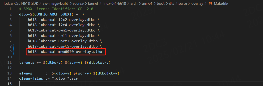
6.5.3.1. 编译设备树插件
前面介绍了在内核源码/arch/arm64/boot/dts/sunxi/overlay/目录下添加h618-lubancat-mpu6050-overlay.dts设备树插件, 为编译该设备树插件需要在内核源码/arch/arm64/boot/dts/sunxi/overlay/目录下的Makefile添加编译该设备树配置,如下图所示:
在内核源码顶层目录执行以下命令编译设备树插件:
#加载配置文件
make ARCH=arm64 CROSS_COMPILE=aarch64-linux-gnu- linux_h618_defconfig
#使用dtbs参数单独编译设备树
make ARCH=arm64 -j4 CROSS_COMPILE=aarch64-linux-gnu- dtbs
编译成功后生成的设备树插件文件 h618-lubancat-mpu6050-overlay.dtbo 位于内核源码/arch/arm64/boot/dts/sunxi/overlays/目录下
6.5.3.2. 编译驱动程序和应用程序
可参考配套源码linux_driver/i2c_mpu6050/目录下的文件,Makefile和前面章节大致相同,如下:
1 2 3 4 5 6 7 8 9 10 11 12 13 14 15 16 17 18 | KERNEL_DIR=../../kernel/
ARCH=arm64
CROSS_COMPILE=aarch64-linux-gnu-nu-
export ARCH CROSS_COMPILE
obj-m := i2c_mpu6050.o
CFLAGS_i2c_mpu6050.o := -fno-stack-protector
out = 6050_test_app
all:
$(MAKE) -C $(KERNEL_DIR) M=$(CURDIR) modules
$(CROSS_COMPILE)gcc -o $(out) $(out).c
.PHONE:clean
clean:
$(MAKE) -C $(KERNEL_DIR) M=$(CURDIR) clean
rm $(out)
|
编译得到i2c_mpu6050.ko驱动模块和6050_test_app应用程序。
6.5.4. 程序运行结果
6.5.4.1. 加载设备树插件
可以通过SCP、NFS或者sftp等将编译好的设备树插件拷贝到开发板上。然后把设备树插件 h618-lubancat-mpu6050-overlay.dtbo 复制到 /boot/dtb/sunxi/overlay/ 目录下。
打开/boot/uEnv.txt文件,添加设备树插件配置,如图所示:
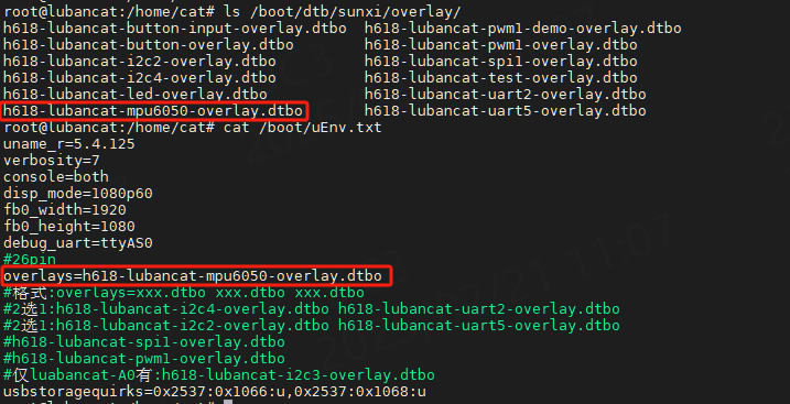
重启开发板,设备树插件加载成功后会有:
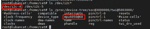
6.5.4.2. 测试效果
将先前编译好的i2c_mpu6050.ko驱动及测试6050_test_app上传至开发板中。
加载i2c_mpu6050.ko,改变mpu6050的姿态,运行6050_test_app即可看到如下效果。
1 2 3 4 5 6 7 8 | #加载驱动
sudo insmod i2c_mpu6050.ko
#查看设备文件
ls /dev/I2C1_mpu6050
#运行应用程序
sudo ./6050_test_app
|
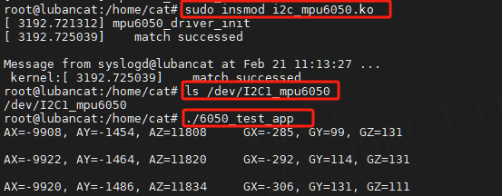
注意:这里采集的是原始数据,所以波动较大是正常的。