
8. linux电源管理
在linux内核中电源管理(Power Management)是个庞大的系统,管理系统的电源,一般是在不用时关闭电源或将系统切换到低功耗状态。实际可以分为电源状态管理和省电管理, 涉及管理电源供电、电源状态管理、运行时的电源管理、电源省电管理、低功耗等等。
电源的状态管理,就是我们平常使用开机、关机和重启等。具体来讲有:睡眠(Sleep)也叫做Suspend to RAM(STR),把系统的状态信息保存到内存, 内存供电,其他断电,在内核中睡眠也称作Suspend;休眠(Hibernate)也叫做Suspend to Disk(STD),把系统的状态信息保存到磁盘,系统都断电
重启(Restart)和关机(Shutdown),比较简单,就是不再使用系统,或者是重新启动系统,在系统中使用命令reboot、halt、poweroff等就行重启或者关机, 这些命令都会发起reboot系统调用,然后实现操作,有兴趣可以自行去了解下Reboot系统调用。
除了上面的一些,电源还有省电管理,有CPU动态调频(CPUFreq)、设备动态调频(DevFreq)、CPUIdle、CPU Hotplug、Runtime PM、PM QoS等。 CPU动态调频和设备动态调频,通过降低频率进行省电,同时兼顾性能和负载进行调节。CPUIdle是当某个CPU上没有进程可调度的时候可以暂时局部关掉这个CPU的电源,有进程时再启用。
CPU Hotplug指的是我们可以把某个CPU热移除,然后系统就不会再往这个CPU上派任务了, 这个CPU就可以放心地完全关闭电源了,当把这个CPU再热插入之后,就对这个CPU恢复供电,这个CPU就可以正常执行任务了。 Runtime PM指的是设备的动态电源管理,系统中存在很多设备,但是并不是每种设备都在一直使用,可以在不用的时候关闭设备的电源,减少功耗。
本章主要介绍系统的Suspend和Regulator Framework。
本章配套源码位于:linux_driver/power_management
8.1. Suspend
从用户角度看,系统可以休眠sleep或者休眠(Hibernate),实际都是保存系统上下文,然后挂起(suspend)系统,之后那肯定就有唤醒(wakeup)。 suspend的详细过程较复杂涉及许多模块,我们就简单介绍下suspend相关的用户接口。
Linux Kernel支持的休眠方式,可以使用想下面命令查看:
1 | cat /sys/power/state
|
/sys/power/state文件用于将系统置于指定的电源状态(freeze,standby, mem, disk),有些系统是不会全部有的,一般会有其中一种或者几种。 用户空间往该文件写入特定的电源状态字符串,将会把系统置为该模式,这几种状态的解释如下:
freeze
冻结I/O设备,将它们置于低功耗状态,使处理器进入空闲状态,处于S2Idle状态下时,设备中断就可以将其唤醒。
Standby
除了冻结I/O设备外,还会暂停系统。由于系统核心逻辑单元保持上电状态,操作的状态不会丢失,也会很容易恢复到之前的状态。 处于Standby状态时,可能需要依赖平台来设置唤醒源。
mem
运行状态数据存到内存,并关闭外设,进入等待模式,除了Memory需要进行自刷新来保持数据外,其他的所有设备都需要进入到低功耗状态,就是STR(Suspend to RAM)。除了实现Standby中的操作外,还有一些平台相关的操作要进行。 由于存在掉电行为,因此Resume的时候需要重新进行配置,唤醒过程较慢,处于STR状态时,需要依赖平台设置唤醒源。
disk
这个操作会将运行时的context保存在Disk这种非易失的存储器中,然后进行掉电操作,就是STD(Suspend-to-Disk)。比如当按下电源键进行唤醒时,然后恢复,唤醒过程最慢。
上面四种状态,功耗节省效果依次增强,同时唤醒回来的时间开销也相应加大。
8.2. Regulator Framework
Regulator翻译为”调节器”,分为电压调节器(voltage regulator)和电流调节器(current regulator),是电源管理的底层基础设施之一,在内核中regulator实际是个抽象出来的概念。
在linux中regulator Framework框架设计,控制系统中某些设备的电压/电流供应,并且在系统运行的过程中,动态改变regulators的输出,以达到省电的目的。 该Regulator框架为各种使用电源的设备(consumer)提供统一接口,允许获取电压,限制电压,使能和关闭电源等操作,也提供了Regulator驱动接口, 允许注册电源提供者(provider)并向内核提供操作函数等。
Linux Regulator Framework整体分为四个部分,分别是machine(regulator硬件制约,映射关系等),regulator(理解为regulator driver), consumer(regulator的使用者,服务对象),sys-class-regulator(用户空间接口)。
8.2.1. Regulator驱动
Regulator驱动主要是电源提供者(provider)注册和通过相关操作函数,电源提供者(provider)是PMIC等。下面介绍下注册接口函数和数据结构:
struct regulator_desc结构体用来描述一个独立的PMIC提供的每个调节器,一个静态描述。
1 2 3 4 5 6 7 8 9 10 11 12 13 14 15 16 17 18 | struct regulator_desc {
const char *name;
const char *supply_name;
const char *of_match;
const char *regulators_node;
/*..................*/
int id;
unsigned n_voltages;
const struct regulator_ops *ops;
int irq;
enum regulator_type type;
struct module *owner;
unsigned int min_uV;
unsigned int uV_step;
unsigned int ramp_delay;
/*..................*/
};
|
上面结构体有省略,详细请看内核源码/include/linux/regulator/driver.h,有详细的注释。
name: Regulator的名字
supply_name :该regulator parent的name,在级联时使用
of_match:匹配设备树中的regulator名字
regulators_node:自动从DTS中解析init_data
id:regulator的标识
n_voltages :regulator可用的选择器输出数量,固定输出电压,应将n_voltage设置为1
ops:一组操作函数,回调函数,用来操作电源管理,注册regulator资源,会指定
type: 表示regulator是电压调节器还是电流调节器。
min_uV: 表示regulator输出的最小电压
ramp_delay : 电压改变后稳定下来所需时间
1 2 3 4 | struct regulator_dev *regulator_register(struct regulator_desc *regulator_desc,
const struct regulator_config *config);
void regulator_unregister(struct regulator_dev *rdev);
|
regulator_register函数是注册regulator的接口,传入regulator_desc和regulator_config两个结构体参数,regulator_desc描述regulator以及相关操作函数, regulator_config主要包含一些调节器描述的可变元素和一些约束,一种安全限制等。返回一个regulator_dev结构体,该结构体是一个抽象的描述对regulator,如下(有省略):
1 2 3 4 5 6 7 8 9 10 11 12 13 14 15 16 17 18 19 20 21 22 23 24 25 26 27 28 29 30 31 | struct regulator_dev {
const struct regulator_desc *desc;
int exclusive;
u32 use_count;
u32 open_count;
u32 bypass_count;
/* lists we belong to */
struct list_head list; /* list of all regulators */
/* lists we own */
struct list_head consumer_list; /* consumers we supply */
struct coupling_desc coupling_desc;
struct blocking_notifier_head notifier;
struct mutex mutex; /* consumer lock */
struct task_struct *mutex_owner;
int ref_cnt;
struct module *owner;
struct device dev;
struct regulation_constraints *constraints;
struct regulator *supply; /* for tree */
const char *supply_name;
struct regmap *regmap;
struct delayed_work disable_work;
int deferred_disables;
void *reg_data; /* regulator_dev data */
/*..................*/
};
|
list:regulator链表。
consumer_list:该regulator下所有的consumer。
notifier: regulator的通知链,用于给consumer通知event。
constraints:结构体regulation_constraints结构对regulator施加的一些的限制,是一种安全限制。结构体如下(有省略):
1 2 3 4 5 6 7 8 9 10 11 12 13 14 15 16 17 18 19 20 21 22 23 24 25 26 27 28 29 30 31 32 33 34 35 36 37 38 39 40 | struct regulation_constraints {
const char *name;
/*电压输出范围 */
int min_uV;
int max_uV;
int uV_offset;
/* 电流输出范围 */
int min_uA;
int max_uA;
int ilim_uA;
int system_load;
/* used for coupled regulators */
int max_spread;
/* 标志对这个regulator有效的操作模式*/
unsigned int valid_modes_mask;
/* regulator有效的操作 */
unsigned int valid_ops_mask;
/* regulator input voltage - only if supply is another regulator */
int input_uV;
/*.......................*/
/* 约束标志位 */
unsigned always_on:1; /* 当系统开启时,regulator不会关闭 */
unsigned boot_on:1; /* bootloader/firmware enabled regulator */
unsigned apply_uV:1; /* 当电压最大值等于最小值,使能约束,是固定的电压*/
unsigned ramp_disable:1; /* disable ramp delay */
unsigned soft_start:1; /* ramp voltage slowly */
unsigned pull_down:1; /* pull down resistor when regulator off */
unsigned over_current_protection:1; /* auto disable on over current */
}
|
该结构体是一个安全限制,比如是电压调节器,限制了电压的输出范围等,这些一般在设备树描述,比如min_uA对应设备树的“regulator-min-microvolt”属性。
8.2.2. consumer接口函数
consumer是regulator提供服务的对象,使用者。每个consumer都有个结构体:
1 2 3 4 5 6 7 8 9 10 11 12 | struct regulator {
struct device *dev;
struct list_head list;
unsigned int always_on:1;
unsigned int bypass:1;
int uA_load;
struct regulator_voltage voltage[REGULATOR_STATES_NUM];
const char *supply_name;
struct device_attribute dev_attr;
struct regulator_dev *rdev; //关联的regulator
struct dentry *debugfs;
};
|
常见的consumer接口函数:
1 2 3 4 5 6 7 8 9 10 11 12 13 14 15 16 17 18 19 20 21 22 | /*获取和释放*/
struct regulator *regulator_get(struct device*dev, const char *id);
void regulator_put(struct regulator *regulator);
/*使能和关闭*/
int regulator_enable(regulator);
int regulator_disable(regulator);
/*设置regulator的电压,获得regulator的电压状态*/
int regulator_set_voltage(regulator, min_uVmax_uV)
int regulator_get_voltage(regulator);
int regulator_set_current_limit(regulator, min_uA, max_uA);
/*操作模式控制和状态*/
int regulator_set_optimum_mode(struct regulator*regulator,int load_uA);
int regulator_set_mode(struct regulator*regulator, unsigned int mode);
unsigned int regulator_get_mode(struct regulator*regulator);
|
8.2.3. 用户空间sysfs接口
登录板卡系统,执行 ls -la /sys/class/regulator 命令:
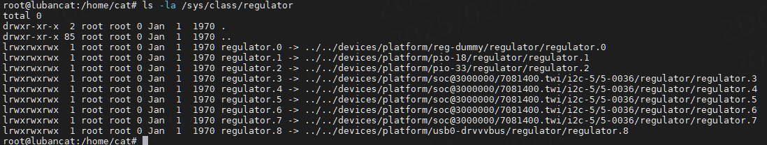
可以看到该目录有我们注册的regulator,并且都是链接文件,指向平台设备下的具体文件。 我们查看regulator.1(pio-18)目录,可以看到一系列文件:
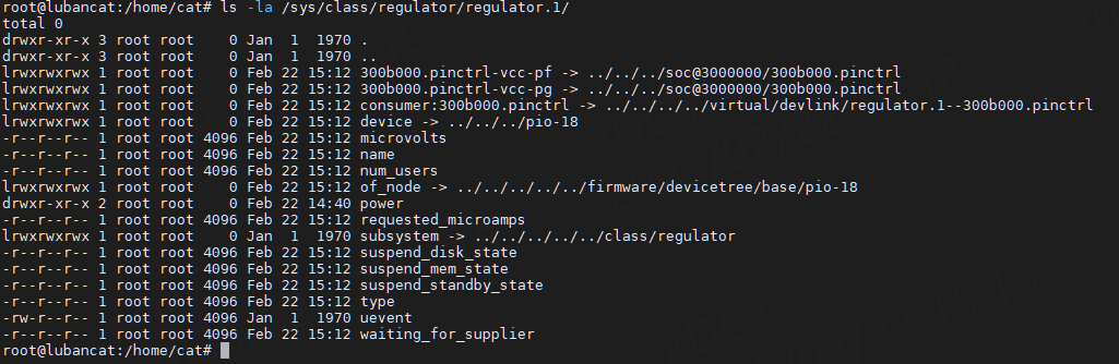
consumer :表示使用该调节器的设备。
device :指向该调节器所属的设备,位于/sys/devices/下的设备目录。
microvolts :当前调节器输出的电压值,单位μV,可以通过读取该文件获取当前电压。
name :调节器的名称。
num_users :当前使用该调节器的设备数量。
of_node :指向设备树中该调节器的节点。
power :电源管理相关的目录。
suspend_standby_state :调节器在系统standby时的状态。
suspend_mem_state :调节器在系统mem时的状态。
suspend_disk_state :调节器在系统disk时的状态。
type :调节器的类型,通常为voltage或current,表示调节器是电压调节器还是电流调节器。
waiting_for_supplier :调节器是否正在等待电源供应,如果值为1,表示调节器正在等待电源供应。
8.3. 源码分析
将regulator.1(pio-18)以为例,简单讲解下其配置,设备树描述如下:
1 2 3 4 5 6 7 8 9 10 11 12 13 14 15 16 17 18 19 20 21 22 23 24 25 26 27 28 29 30 31 32 33 34 35 | pio: pinctrl@300b000 {
compatible = "allwinner,sun50iw9-pinctrl";
reg = <0x0 0x0300b000 0x0 0x400>;
interrupts = <GIC_SPI 51 IRQ_TYPE_LEVEL_HIGH>,
<GIC_SPI 52 IRQ_TYPE_LEVEL_HIGH>,
<GIC_SPI 53 IRQ_TYPE_LEVEL_HIGH>,
<GIC_SPI 43 IRQ_TYPE_LEVEL_HIGH>,
<GIC_SPI 54 IRQ_TYPE_LEVEL_HIGH>,
<GIC_SPI 55 IRQ_TYPE_LEVEL_HIGH>,
<GIC_SPI 56 IRQ_TYPE_LEVEL_HIGH>,
<GIC_SPI 57 IRQ_TYPE_LEVEL_HIGH>;
clocks = <&ccu CLK_APB1>, <&dcxo24M>, <&osc32k>;
clock-names = "apb", "hosc", "losc";
gpio-controller;
#gpio-cells = <3>;
interrupt-controller;
#interrupt-cells = <3>;
vcc-pf-supply = <®_pio1_8>;
vcc-pfo-supply = <®_pio3_3>;
/*....省略...*/
reg_pio1_8: pio-18 {
compatible = "regulator-fixed";
regulator-name = "pio-18";
regulator-min-microvolt = <1800000>;
regulator-max-microvolt = <1800000>;
};
reg_pio3_3: pio-33 {
compatible = "regulator-fixed";
regulator-name = "pio-33";
regulator-min-microvolt = <3300000>;
regulator-max-microvolt = <3300000>;
};
|
以上,reg_pio1_8是一个固定电压调节器作用是为GPIO控制器(pio)的电源域(vcc-pf)提供固定的1.8V电压。
compatible = “regulator-fixed” :表示这是一个固定电压调节器。
regulator-name :调节器的名称,用于标识该调节器。
regulator-min-microvolt和regulator-max-microvolt :指定调节器的输出电压范围。这里设置为1.8V,也即1800000微伏。
查看内核源码/drivers/regulator/fixed.c,可以找到对应的驱动源码,截取部分内容如下:
1 2 3 4 5 6 7 8 9 10 11 12 13 14 15 16 17 18 19 20 21 22 23 | #if defined(CONFIG_OF)
static const struct of_device_id fixed_of_match[] = {
{
.compatible = "regulator-fixed",
.data = &fixed_voltage_data,
},
{
.compatible = "regulator-fixed-clock",
.data = &fixed_clkenable_data,
},
{
},
};
MODULE_DEVICE_TABLE(of, fixed_of_match);
#endif
static struct platform_driver regulator_fixed_voltage_driver = {
.probe = reg_fixed_voltage_probe,
.driver = {
.name = "reg-fixed-voltage",
.of_match_table = of_match_ptr(fixed_of_match),
},
};
|
当匹配到“regulator-fixed”时,调用reg_fixed_voltage_probe函数,进行初始化。
reg_fixed_voltage_probe函数代码如下:
1 2 3 4 5 6 7 8 9 10 11 12 13 14 15 16 17 18 19 20 21 22 23 24 25 26 27 28 29 30 31 32 33 34 35 36 37 38 39 40 41 42 43 44 45 46 47 48 49 50 51 52 53 54 55 56 57 58 59 60 61 62 63 64 65 66 67 68 69 70 71 72 73 74 75 76 77 78 79 80 81 82 83 84 85 86 87 88 89 90 91 92 93 94 95 96 97 98 99 100 101 102 103 104 105 106 107 108 109 110 111 112 113 114 115 116 117 | static int reg_fixed_voltage_probe(struct platform_device *pdev)
{
struct device *dev = &pdev->dev; //指向平台设备的设备结构体
struct fixed_voltage_config *config; //存储固定电压调节器的配置信息
struct fixed_voltage_data *drvdata; //私有数据,用于存储调节器的状态和数据
const struct fixed_dev_type *drvtype = of_device_get_match_data(dev); //设备类型数据,用于区分不同类型的固定电压调节器
struct regulator_config cfg = { }; //调节器配置结构体,用于注册调节器
enum gpiod_flags gflags; //GPIO标志,用于配置使能GPIO的状态
int ret;
drvdata = devm_kzalloc(&pdev->dev, sizeof(struct fixed_voltage_data), //使用devm_kzalloc动态分配驱动私有数据
GFP_KERNEL);
if (!drvdata)
return -ENOMEM;
if (pdev->dev.of_node) {
config = of_get_fixed_voltage_config(&pdev->dev, //从设备树中获取配置信息
&drvdata->desc);
if (IS_ERR(config))
return PTR_ERR(config);
} else {
config = dev_get_platdata(&pdev->dev);
}
if (!config)
return -ENOMEM;
drvdata->desc.name = devm_kstrdup(&pdev->dev, //将配置中的supply_name复制到调节器描述结构体drvdata->desc中
config->supply_name,
GFP_KERNEL);
if (drvdata->desc.name == NULL) {
dev_err(&pdev->dev, "Failed to allocate supply name\n");
return -ENOMEM;
}
drvdata->desc.type = REGULATOR_VOLTAGE; //设置调节器类型为电压调节器
drvdata->desc.owner = THIS_MODULE; //设置调节器所有者为当前模块
if (drvtype && drvtype->has_enable_clock) { //判断设备类型是否支持时钟使能
drvdata->desc.ops = &fixed_voltage_clkenabled_ops; //如果支持则设置调节器操作函数为fixed_voltage_clkenabled_ops
drvdata->enable_clock = devm_clk_get(dev, NULL); //获取时钟。
if (IS_ERR(drvdata->enable_clock)) {
dev_err(dev, "Cant get enable-clock from devicetree\n");
return -ENOENT;
}
} else {
drvdata->desc.ops = &fixed_voltage_ops; //如果不支持则设置调节器操作函数为fixed_voltage_ops
}
drvdata->desc.enable_time = config->startup_delay; //设置调节器的启动延迟时间
if (config->input_supply) { //如果配置中指定了输入电源名称,将其复制到调节器描述结构体中
drvdata->desc.supply_name = devm_kstrdup(&pdev->dev,
config->input_supply,
GFP_KERNEL);
if (!drvdata->desc.supply_name) {
dev_err(&pdev->dev,
"Failed to allocate input supply\n");
return -ENOMEM;
}
}
if (config->microvolts) //如果配置中指定了输出电压,设置调节器的输出电压和电压数量
drvdata->desc.n_voltages = 1;
drvdata->desc.fixed_uV = config->microvolts;
/*
* The signal will be inverted by the GPIO core if flagged so in the
* decriptor.
*/
if (config->enabled_at_boot) //根据配置中的enabled_at_boot设置使能GPIO的初始状态
gflags = GPIOD_OUT_HIGH;
else
gflags = GPIOD_OUT_LOW;
/*
* Some fixed regulators share the enable line between two
* regulators which makes it necessary to get a handle on the
* same descriptor for two different consumers. This will get
* the GPIO descriptor, but only the first call will initialize
* it so any flags such as inversion or open drain will only
* be set up by the first caller and assumed identical on the
* next caller.
*
* FIXME: find a better way to deal with this.
*/
gflags |= GPIOD_FLAGS_BIT_NONEXCLUSIVE;
/*
* Do not use devm* here: the regulator core takes over the
* lifecycle management of the GPIO descriptor.
*/
cfg.ena_gpiod = gpiod_get_optional(&pdev->dev, NULL, gflags);
if (IS_ERR(cfg.ena_gpiod))
return PTR_ERR(cfg.ena_gpiod);
cfg.dev = &pdev->dev; //配置调节器,设置调节器配置结构体cfg的字段
cfg.init_data = config->init_data;
cfg.driver_data = drvdata;
cfg.of_node = pdev->dev.of_node;
drvdata->dev = devm_regulator_register(&pdev->dev, &drvdata->desc, //注册调节器,
&cfg);
if (IS_ERR(drvdata->dev)) {
ret = PTR_ERR(drvdata->dev);
dev_err(&pdev->dev, "Failed to register regulator: %d\n", ret);
return ret;
}
platform_set_drvdata(pdev, drvdata); //将驱动私有数据drvdata与平台设备关联
dev_dbg(&pdev->dev, "%s supplying %duV\n", drvdata->desc.name,
drvdata->desc.fixed_uV);
return 0;
}
|
以上源码中一些配置在reg_pio1_8中没有使用,结合设备树中其他节点查看会比较清晰,例如以下节点:
1 2 3 4 5 6 7 8 9 | usb0_drvvbus: usb0-drvvvbus {
compatible = "regulator-fixed";
regulator-name = "usb0-drvvbus";
regulator-min-microvolt = <5000000>;
regulator-max-microvolt = <5000000>;
regulator-enable-ramp-delay = <1000>;
gpio = <&pio PG 14 GPIO_ACTIVE_HIGH>;
enable-active-high;
};
|
regulator-min-microvolt和regulator-max-microvolt :设置为5V,表示该调节器输出固定的5V电压。
regulator-enable-ramp-delay :指定调节器使能时的电压上升延迟时间,表示调节器使能后,电压会在1毫秒内上升到设定值。
gpio :指定用于控制调节器使能的GPIO引脚,GPIO_ACTIVE_HIGH表示高电平,GPIO_ACTIVE_LOW表示低电平。
enable-active-high :指定 GPIO 的有效电平为高电平,当GPIO为高电平时,调节器使能,当GPIO为低电平时,调节器禁用。
查看LubanCat-A1板卡原理图,可知PG14引脚接在了USB A口电源功率开关的使能脚上,如下图:
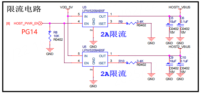
因此,当系统启动时,PG14被快速拉高为高电平,使能USB A口5V电源输出。
8.4. regulators驱动实验
下面我们简单编写一个驱动,向内核注册一个regulators,电压范围为500000µV到1350000µV。
配套源码位于:linux_driver/power_management
8.4.1. 实验代码讲解
1 2 3 4 5 6 7 8 9 10 11 12 13 14 15 16 17 18 19 20 21 22 23 24 25 26 27 28 29 30 31 32 33 34 35 36 37 38 39 40 41 42 43 44 45 46 47 48 49 50 51 52 53 54 55 56 57 58 59 60 61 62 63 64 65 | static int regulator_driver_probe(struct platform_device *pdev)
{
struct regulator_config config = { };
int ret;
config.dev = &pdev->dev;
config.init_data = &my_regulator_initdata;
my_regulator_test_rdev = regulator_register(&my_regulator_desc, &config);
if (IS_ERR(my_regulator_test_rdev)) {
ret = PTR_ERR(my_regulator_test_rdev);
pr_err("Failed to register regulator: %d\n", ret);
return ret;
}
return 0;
}
static struct platform_driver my_regulator_driver = {
.probe = regulator_driver_probe,
.driver = {
.name = "my_regulator",
.owner = THIS_MODULE,
},
};
static struct platform_device *regulator_pdev;
static int my_regulator_test_init(void)
{
int ret;
regulator_pdev = platform_device_alloc("my_regulator", -1);
if (!regulator_pdev) {
pr_err("Failed to allocate dummy regulator device\n");
return -1;
}
ret = platform_device_add(regulator_pdev);
if (ret != 0) {
pr_err("Failed to register dummy regulator device: %d\n", ret);
platform_device_put(regulator_pdev);
return -1;
}
ret = platform_driver_register(&my_regulator_driver);
if (ret != 0) {
pr_err("Failed to register dummy regulator driver: %d\n", ret);
platform_device_unregister(regulator_pdev);
return -1;
}
return 0;
}
static void my_regulator_test_exit(void)
{
regulator_unregister(my_regulator_test_rdev);
platform_device_unregister(regulator_pdev);
platform_driver_unregister(&my_regulator_driver);
}
module_init(my_regulator_test_init);
module_exit(my_regulator_test_exit);
MODULE_LICENSE("GPL");
|
第9行 注册regulator,
第19行 定义平台驱动my_regulator_driver
第29-54行 注册平台驱动和增加平台设备
第56-60行 注销平台设备和平台驱动和regulator
8.4.2. 编译驱动程序
可参考配套源码linux_driver/power_management/目录下的文件,Makefile和前面章节大致相同,如下:
1 2 3 4 5 6 7 8 9 10 11 12 13 14 15 | KERNEL_DIR=../../kernel/
ARCH=arm64
CROSS_COMPILE=aarch64-linux-gnu-
export ARCH CROSS_COMPILE
obj-m := regulator_test.o
CFLAGS_regulator_test.o := -fno-stack-protector
all:
$(MAKE) -C $(KERNEL_DIR) M=$(CURDIR) modules
.PHONE:clean
clean:
$(MAKE) -C $(KERNEL_DIR) M=$(CURDIR) clean
|
编译得到regulator_test.ko驱动模块。
8.4.3. 程序运行结果
将regulator_test.ko驱动模块传到板卡,执行命令加载驱动,
1 | sudo insmod regulator_test.ko
|
加载之后,/sys/class/regulator下会生成一个regulator,后缀数字根据实际的确定。
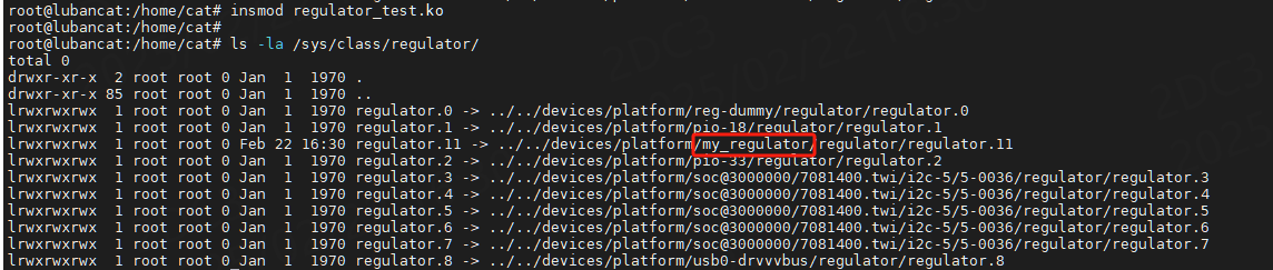
在/sys/kernel/debug/regulator/regulator_summary文件中记录系统regulator和consumer之间的关系,如下图:
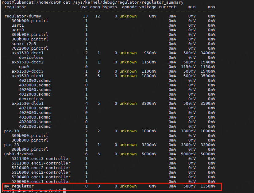
可以看到my_regulator调节器的最小电压为500mV,最大电压为1350mV。
8.5. 参考
内核文档:
Documentation/devicetree/bindings/regulator/regulator.txt
Documentation/ABI/testing/sysfs-class-regulator