13. RS485使用
RS485的使用与串口终端的使用基本相同,差别在于使用485时需要手动切换485芯片的收发引脚。
13.1. 使能RS485设备树插件
485-1、485-2虽然也是使用串口1和串口3,但他们设备树作用并不相同, 因此需要先将串口1、串口3相关设备树插件关闭,再使能485的设备树插件。 修改 boot/uEnv.txt 文件,找到uart、485相关设备树插件修改如下:
1 2 3 4 5 | #dtoverlay=/usr/lib/linux-image-4.19.94-stm-r1/overlays/stm-fire-usart1.dtbo
#dtoverlay=/usr/lib/linux-image-4.19.94-stm-r1/overlays/stm-fire-usart3.dtbo
dtoverlay=/usr/lib/linux-image-4.19.94-stm-r1/overlays/stm-fire-485r1.dtbo
dtoverlay=/usr/lib/linux-image-4.19.94-stm-r1/overlays/stm-fire-485r2.dtbo
|
13.2. 简单测试485功能
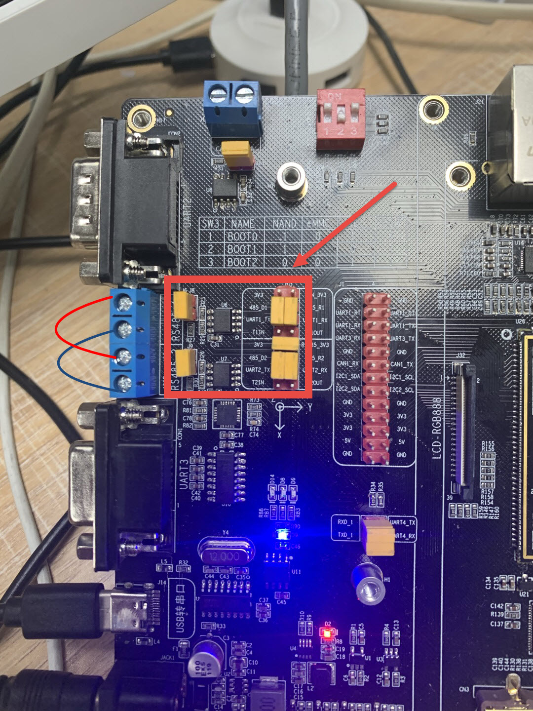
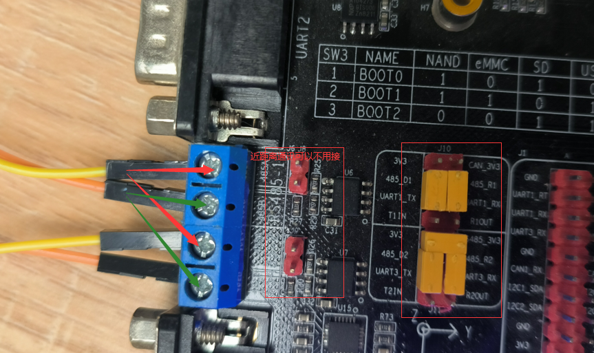
修改 boot/uEnv.txt 之后重启开发板,并 将开发板中484总线的跳帽连接上(在开发板的左上角区域), 接着将485接口按照下图所示的方法对接,485-1的A端与485-2的A端对接,485-1的B端与485-2的B端对接。

查看485总线设备
1 2 3 4 5 | root@npi:~# ls -l /dev/ttySTM*
crw------- 1 root tty 246, 0 Mar 6 06:47 /dev/ttySTM0
crw-rw---- 1 root dialout 246, 1 Mar 6 06:46 /dev/ttySTM1
crw-rw---- 1 root dialout 246, 3 Mar 6 06:46 /dev/ttySTM3
root@npi:~#
|
其中ttySTM1为485-1设备,tttySTM3为485-2设备。
STM32MP157开发板板载485芯片原理图如下

其中控制RS485-1的收发引脚 USART1_CTS 为 PZ3 , 控制RS485-2的收发引脚 USART1_RTS 为 PZ5 。 当设置引脚为低电平是为接收数据,设置高电平为发送数据。
将PZ3引脚为低电平,设置485-1为接收模式。 设置PZ5引脚为高电平,设置485-2为发送模式。
1 2 3 4 5 | #设置PZ3引脚为低电平
root@npi:~# gpioset 9 3=0
#设置PZ5引脚为高电平
root@npi:~# gpioset 9 5=1
|
打开两个不同的终端,一个用于读取设备数据,一个用于发送设备数据
1 2 | #读取485-1数据
cat /dev/ttySTM1
|
1 2 | #485-2发送数据
echo "123456" > /dev/ttySTM3
|
此时在终端1中将会接收到终端2传来的数据,此处仅做简单操作,其他使用方式同串口章节相同,可参考串口章节。
13.3. libmodbus简介和测试
libmodbus是一个与使用modbus协议的设备进行数据 发送/接收 的库, 它包含各种后端(backends)通过不同网络进行通信 (例如,RTU模式下的串口、485总线或TCP / IPv6中的以太网)。 libmodbus还提供了较低通信层的抽象,并在所有支持的平台上提供相同的API。
libmodbus是开源的,它遵循 LGPL v2.1 开源协议,这个协议没有GPL协议那么严格, 简单来说,只要你不修改libmodbus库里面的东西(只调用、链接该库),你是可以闭源你的代码的, 你也可以用于商业用途,这是非常好的。
13.3.1. 使用libmodbus简单测试485通讯
开发准备,在开发板系统上安装libmodbus-dev和一些编译工具。
1 2 | sudo apt update
sudo apt install gcc git libmodbus-dev pkg-config
|
将开发板的串口和485连接,两个485连接:

13.3.2. 程序
1.服务端程序
1 2 3 4 5 6 7 8 9 10 11 12 13 14 15 16 17 18 19 20 21 22 23 24 25 26 27 28 29 30 31 32 33 34 35 36 37 38 39 40 41 42 43 44 45 46 47 48 49 50 51 52 53 54 55 56 57 58 59 60 61 62 63 64 65 66 67 68 69 70 71 72 73 74 75 76 77 78 79 80 81 82 83 84 85 86 87 88 89 90 91 92 93 94 95 96 97 98 99 100 101 102 103 104 105 106 107 108 109 110 111 112 113 114 115 116 117 118 119 120 121 122 123 124 125 126 127 128 129 130 131 | #include <stdio.h>
#include <unistd.h>
#include <string.h>
#include <stdlib.h>
#include <errno.h>
#include <modbus.h>
#include <sys/stat.h>
#include <fcntl.h>
#define SERVER_GPIO_INDEX "403"
#define SERVER_ID 17
const uint16_t UT_REGISTERS_TAB[] = { 0x0A, 0x0E, 0x0A, 0x1B,0x0A};
static int _server_ioctl_init(void)
{
int fd;
//index config
fd = open("/sys/class/gpio/export", O_WRONLY);
if(fd < 0)
return 1;
write(fd, SERVER_GPIO_INDEX, strlen(SERVER_GPIO_INDEX));
close(fd);
//direction config
fd = open("/sys/class/gpio/gpio" SERVER_GPIO_INDEX "/direction", O_WRONLY);
if(fd < 0)
return 2;
write(fd, "out", strlen("out"));
close(fd);
return 0;
}
static int _server_ioctl_on(void)
{
int fd;
fd = open("/sys/class/gpio/gpio" SERVER_GPIO_INDEX "/value", O_WRONLY);
if(fd < 0)
return 1;
write(fd, "1", 1);
close(fd);
return 0;
}
static int _server_ioctl_off(void)
{
int fd;
fd = open("/sys/class/gpio/gpio" SERVER_GPIO_INDEX "/value", O_WRONLY);
if(fd < 0)
return 1;
write(fd, "0", 1);
close(fd);
return 0;
}
static void _modbus_rtu_server_ioctl(modbus_t *ctx, int on)
{
if (on) {
_server_ioctl_on();
} else {
_server_ioctl_off();
}
}
int main(int argc, char*argv[])
{
modbus_t *ctx;
modbus_mapping_t *mb_mapping;
int rc;
int i;
uint8_t *query;
/*设置串口信息*/
ctx = modbus_new_rtu("/dev/ttySTM1", 9600, 'N', 8, 1);
_server_ioctl_init();
/*设置从机地址,设置485模式*/
modbus_set_slave(ctx, SERVER_ID);
modbus_rtu_set_custom_rts(ctx, _modbus_rtu_server_ioctl);
modbus_rtu_set_rts(ctx, MODBUS_RTU_RTS_UP);
modbus_rtu_set_serial_mode(ctx, MODBUS_RTU_RS485);
query = malloc(MODBUS_RTU_MAX_ADU_LENGTH);
/*开启调试*/
modbus_set_debug(ctx, TRUE);
mb_mapping = modbus_mapping_new_start_address(0,0,0,0,0,5,0,0);
if (mb_mapping == NULL) {
fprintf(stderr, "Failed to allocate the mapping: %s\n",
modbus_strerror(errno));
modbus_free(ctx);
return -1;
}
/* 初始化值 */
for (i=0; i < 5; i++) {
mb_mapping->tab_registers[i] = UT_REGISTERS_TAB[i];
}
rc = modbus_connect(ctx);
if (rc == -1) {
fprintf(stderr, "Unable to connect %s\n", modbus_strerror(errno));
modbus_free(ctx);
return -1;
}
modbus_flush(ctx);
for (;;) {
do {
rc = modbus_receive(ctx, query);
} while (rc == 0);
rc = modbus_reply(ctx, query, rc, mb_mapping);
if (rc == -1) {
break;
}
}
modbus_mapping_free(mb_mapping);
free(query);
modbus_close(ctx);
modbus_free(ctx);
return 0;
}
|
2.客户端程序
1 2 3 4 5 6 7 8 9 10 11 12 13 14 15 16 17 18 19 20 21 22 23 24 25 26 27 28 29 30 31 32 33 34 35 36 37 38 39 40 41 42 43 44 45 46 47 48 49 50 51 52 53 54 55 56 57 58 59 60 61 62 63 64 65 66 67 68 69 70 71 72 73 74 75 76 77 78 79 80 81 82 83 84 85 86 87 88 89 90 91 92 93 94 95 96 97 98 99 100 101 102 103 104 105 106 107 108 109 110 111 112 113 114 115 116 117 118 119 120 121 | #include <stdio.h>
#include <unistd.h>
#include <string.h>
#include <stdlib.h>
#include <errno.h>
#include <modbus.h>
#include <sys/stat.h>
#include <fcntl.h>
#define CLIENT_GPIO_INDEX "405"
#define SERVER_ID 17
static int _client_ioctl_init(void)
{
int fd;
//index config
fd = open("/sys/class/gpio/export", O_WRONLY);
if(fd < 0)
return 1 ;
write(fd, CLIENT_GPIO_INDEX, strlen(CLIENT_GPIO_INDEX));
close(fd);
//direction config
fd = open("/sys/class/gpio/gpio" CLIENT_GPIO_INDEX "/direction", O_WRONLY);
if(fd < 0)
return 2;
write(fd, "out", strlen("out"));
close(fd);
return 0;
}
static int _client_ioctl_on(void)
{
int fd;
fd = open("/sys/class/gpio/gpio" CLIENT_GPIO_INDEX "/value", O_WRONLY);
if(fd < 0)
return 1;
write(fd, "0", 1);
close(fd);
return 0;
}
static int _client_ioctl_off(void)
{
int fd;
fd = open("/sys/class/gpio/gpio" CLIENT_GPIO_INDEX "/value", O_WRONLY);
if(fd < 0)
return 1;
write(fd, "1", 1);
close(fd);
return 0;
}
static void _modbus_rtu_client_ioctl(modbus_t *ctx, int on)
{
if (on) {
_client_ioctl_on();
} else {
_client_ioctl_off();
}
}
int main(int argc, char *argv[])
{
modbus_t *ctx = NULL;
int i,rc;
uint16_t tab_rp_registers[5] = {0}; //定义存放数据的数组
/*创建一个RTU类型的变量*/
/*设置要打开的串口设备 波特率 奇偶校验 数据位 停止位*/
ctx = modbus_new_rtu("/dev/ttySTM3", 9600, 'N', 8, 1);
if (ctx == NULL) {
fprintf(stderr, "Unable to allocate libmodbus context\n");
return -1;
}
/*设置485模式*/
_client_ioctl_init();
modbus_rtu_set_custom_rts(ctx, _modbus_rtu_client_ioctl);
modbus_rtu_set_rts(ctx, MODBUS_RTU_RTS_DOWN);
modbus_rtu_set_serial_mode(ctx, MODBUS_RTU_RS485);
/*设置debug模式*/
modbus_set_debug(ctx, TRUE);
/*设置从机地址*/
modbus_set_slave(ctx, SERVER_ID);
/*RTU模式 打开串口*/
if (modbus_connect(ctx) == -1) {
fprintf(stderr, "Connection failed: %s\n", modbus_strerror(errno));
modbus_free(ctx);
return -1;
}
//读取多个连续寄存器
rc = modbus_read_registers(ctx, 0, 5, tab_rp_registers);
if (rc == -1)
{
fprintf(stderr,"%s\n", modbus_strerror(errno));
return -1;
}
for (i=0; i<5; i++)
{
//打印读取的数据
printf("reg[%d] = %d(0x%x)\n", i, tab_rp_registers[i], tab_rp_registers[i]);
}
modbus_close(ctx);
modbus_free(ctx);
return 0;
}
|
13.3.3. 编译和运行
将两个程序的源文件传输到开发板系统,然后使用下面命令编译:
1 2 | gcc test-server.c -o test-server `pkg-config --cflags --libs libmodbus`
gcc test-client.c -o test-client `pkg-config --cflags --libs libmodbus`
|
打开两个终端,一个用于运行服务端一个用于运行客户端(ssh终端和串口终端)。如下所示:
debian@lubancat:~$./test-server
debian@lubancat:~$./test-client
在客户终端中最终打印
1 2 3 4 5 6 7 8 9 10 11 12 | debian@lubancat:~$ ./utest-client
Opening /dev/ttySTM3 at 9600 bauds (N, 8, 1)
[11][03][00][00][00][05][87][59]
Sending request using RTS signal
Waiting for a confirmation...
<11><03><0A><00><0A><00><0E><00><0A><00><1B><00><0A><E3><47>
reg[0] = 10(0xa)
reg[1] = 14(0xe)
reg[2] = 10(0xa)
reg[3] = 27(0x1b)
reg[4] = 10(0xa)
debian@lubancat:~$
|
在服务终端中最终打印
1 2 3 4 5 6 7 8 | debian@lubancat:~$ ./test-server
Opening /dev/ttySTM1 at 9600 bauds (N, 8, 1)
Bytes flushed (0)
Waiting for a indication...
<11><03><00><00><00><05><87><59>
[11][03][0A][00][0A][00][0E][00][0A][00][1B][00][0A][E3][47]
Sending request using RTS signal
Waiting for a indication...
|
重要
简单测试485功能请按照13.2小节,使用libmodbus测试具体用法请读者自行研究。 参考资料: https://github.com/stephane/libmodbus
13.4. RS485设备树
官方参考文档: 内核源码/Documentation/devicetree/bindings/serialt 目录下的 rs485.txt、fsl-imx-uart.txt、serial.txt 。
野火imx6ull提供了很多的设备树插件源码,若想要添加或修改不同的引脚作为485引脚, 可参考 野火设备树插件GitHub仓库
仓库中提供了485-1、485-2的设备树插件, 其中485-1的设备树插件文件为 imx-fire-485r1-overlay.dts ,源码如下所示
1 2 3 4 5 6 7 8 9 10 11 12 13 14 15 16 17 18 19 20 21 22 23 24 25 26 27 28 29 30 31 32 33 34 35 36 37 38 39 40 41 42 43 44 45 46 47 48 49 50 51 52 53 54 55 56 | /dts-v1/;
/plugin/;
#include <dt-bindings/pinctrl/stm32-pinfunc.h>
#include <dt-bindings/input/input.h>
#include <dt-bindings/mfd/st,stpmic1.h>
/{
fragment@0 {
target=<&pinctrl_z>;
__overlay__ {
usart1_pins_a: usart1-0 {
pins1 {
pinmux = <STM32_PINMUX('Z', 7, AF7)>;/* USART1_TX */
bias-disable;
drive-push-pull;
slew-rate = <0>;
};
pins2 {
pinmux = <STM32_PINMUX('Z', 6, AF7)>; /* USART1_RX */
bias-disable;
};
};
usart1_idle_pins_a: usart1-idle-0 {
pins1 {
pinmux = <STM32_PINMUX('Z', 7, ANALOG)>; /* USART1_TX */
};
pins2 {
pinmux = <STM32_PINMUX('Z', 6, AF7)>; /* USART1_RX */
bias-disable;
};
};
usart1_sleep_pins_a: usart1-sleep-0 {
pins {
pinmux = <STM32_PINMUX('Z', 7, ANALOG)>, /* USART1_TX */
<STM32_PINMUX('Z', 6, ANALOG)>; /* USART1_RX */
};
};
};
};
fragment@1 {
target=<&usart1>;
__overlay__ {
pinctrl-names = "default", "sleep", "idle";
pinctrl-0 = <&usart1_pins_a>;
pinctrl-1 = <&usart1_sleep_pins_a>;
pinctrl-2 = <&usart1_idle_pins_a>;
linux,rs485-enabled-at-boot-time;
status = "okay";
};
};
};
|
485设备树插件修改相对简单,若想修改相对应的引脚,只需修改上面代码颜色部分即可。
