
12. Linux内核电源管理
在Linux系统中,电源管理是保障设备稳定运行、延长续航能力的核心技术,尤其对于移动设备、物联网终端等依赖电池供电的场景,高效的电源管理直接决定设备的使用体验和可靠性。 Linux内核从2.6版本开始逐步完善电源管理体系,形成了一套涵盖“运行时电源管理(Runtime PM)、系统级电源管理(System PM)、动态电源管理(Dynamic PM)”的完整框架, 能够根据设备负载动态调整电源状态,实现节能与性能的平衡。
12.1. 电源管理核心概念
12.1.1. 电源管理定义
Linux内核电源管理(Power Management, PM)是一套内核子系统,其核心目标是在保证设备功能正常的前提下,最大限度降低系统功耗,同时兼顾系统响应速度和性能。 它通过对硬件设备、CPU、内存等系统资源的电源状态进行动态管理,实现“按需供电”——当设备闲置时,切换到低功耗状态;当设备需要工作时,快速唤醒至正常工作状态。
内核电源管理覆盖系统运行的全流程,从设备的运行时状态调整,到系统整体的休眠与唤醒,再到电源调节器的电压/电流控制,形成了分层、模块化的架构,便于驱动开发者集成和扩展。
12.1.2. 电源管理分类
Linux内核电源管理主要分为三大类,覆盖不同层面的电源控制需求:
运行时电源管理(Runtime PM):最常用的电源管理方式,针对单个设备(如GPIO、I2C等),在设备闲置时自动进入低功耗状态(如关闭电源、降低电压),需要工作时快速唤醒,不影响系统整体运行,是嵌入式设备节能的核心手段。
系统级电源管理(System PM):针对整个系统的电源状态,包括休眠(Suspend)和唤醒(Resume),系统休眠时,大部分硬件设备关闭电源,仅保留必要的唤醒电路(如RTC、GPIO),唤醒时恢复所有设备的正常状态,适用于设备长时间闲置的场景。
动态电源管理(Dynamic PM):基于系统负载动态调整硬件参数,如CPU频率(CPUFreq)、CPU电压(CPUVoltage)、电源调节器输出电压等,实现“负载越高,性能越强,功耗越高;负载越低,性能降低,功耗越低”的动态平衡。
12.2. 电源管理机制
12.2.1. 运行时电源管理机制
Runtime PM的核心机制是“引用计数管理”,每个设备都维护一个PM引用计数,通过引用计数的增减控制设备的电源状态:
当设备被使用时(如应用层访问、内核驱动操作),引用计数增加(+1),设备被唤醒至正常工作状态(active)。
当设备停止使用时,引用计数减少(-1),当引用计数为0时,设备自动进入低功耗状态(suspended)。
内核提供自动挂起(autosuspend)机制,可设置延迟时间,当设备闲置超过延迟时间后,自动触发低功耗状态切换。
Runtime PM的状态切换由驱动层实现的回调函数控制,内核提供统一的接口供驱动调用,无需开发者手动管理状态切换细节。
12.2.2. 系统级休眠唤醒机制
系统级休眠分为三个核心阶段,唤醒为休眠的逆过程:
冻结阶段(Freeze):内核冻结所有用户态进程和内核线程,保存进程的运行状态,避免数据丢失。
休眠阶段(Suspend):依次关闭系统中所有外设的电源,配置CPU进入低功耗模式(如深度休眠),仅保留唤醒源(如GPIO、RTC)的供电。
唤醒阶段(Resume):唤醒源触发后,依次启动外设电源,恢复CPU正常工作模式,解冻进程,恢复系统至休眠前的状态。
系统级休眠唤醒的核心是“状态保存与恢复”,内核提供统一的框架,驱动开发者只需实现对应的回调函数,完成设备自身的状态保存与恢复。
12.2.3. 动态电源管理机制
动态电源管理(Dynamic PM)是Linux内核电源管理的核心机制之一,其基于系统实时负载动态调整硬件设备的运行参数,无需手动干预,即可实现“负载与功耗、性能的动态平衡”。
实现方式:动态PM通过内核子系统协同工作,核心调整对象包括CPU、电源调节器、外设等,常见实现方式有:CPU频率动态调整(CPUFreq子系统)、CPU电压动态调整(CPUVoltage子系统)、电源调节器输出电压/电流动态调整(Regulator子系统),多子系统联动实现全系统负载适配。
调整逻辑:内核通过负载检测模块(如CPU负载统计、外设使用状态监测)实时获取系统负载数据,结合预设的策略(如性能优先、节能优先、平衡模式),自动触发硬件参数调整,整个过程无感知且高效,不影响系统正常运行。
动态PM的核心优势的是“按需分配功耗”,区别于运行时PM的“闲置休眠”和系统级PM的“整体休眠”,其可在系统运行过程中实时调整,兼顾响应速度与节能效果。
12.3. 电源管理核心结构体
Linux内核电源管理的核心结构体均定义于相关头文件中,以下讲解驱动开发中最常用的结构体。
12.3.1. 设备电源管理操作集结构体
设备电源管理操作集结构体(struct dev_pm_ops)是设备电源管理的核心操作集,驱动开发者通过实现该结构体的回调函数,控制设备的电源状态切换。
1 2 3 4 5 6 7 8 9 10 11 12 13 | struct dev_pm_ops {
/* 系统级休眠回调:设备休眠前执行,用于保存设备状态 */
int (*suspend)(struct device *dev);
/* 系统级唤醒回调:设备唤醒后执行,用于恢复设备状态 */
int (*resume)(struct device *dev);
/* 运行时PM休眠回调:设备进入运行时低功耗状态前执行 */
int (*runtime_suspend)(struct device *dev);
/* 运行时PM唤醒回调:设备从运行时低功耗状态唤醒后执行 */
int (*runtime_resume)(struct device *dev);
/* 运行时PM空闲回调:设备闲置时执行,判断是否需要进入低功耗状态 */
int (*runtime_idle)(struct device *dev);
/* 其他成员省略 */
};
|
其中,runtime_suspend和runtime_resume是Runtime PM的核心回调,suspend和resume是系统级休眠唤醒的核心回调,开发者可根据需求实现对应回调。
12.3.1.1. SET_RUNTIME_PM_OPS宏
SET_RUNTIME_PM_OPS宏是内核提供的便捷接口,用于快速初始化struct dev_pm_ops结构体中的Runtime PM相关回调函数,无需手动赋值,简化驱动开发者对Runtime PM操作集的配置。
1 | SET_RUNTIME_PM_OPS(suspend_fn, resume_fn, idle_fn)
|
参数说明:
suspend_fn:指向Runtime PM休眠回调函数的指针,对应struct dev_pm_ops中的runtime_suspend成员,设备进入运行时低功耗状态前执行。
resume_fn:指向Runtime PM唤醒回调函数的指针,对应struct dev_pm_ops中的runtime_resume成员,设备从运行时低功耗状态唤醒后执行。
idle_fn:指向Runtime PM空闲回调函数的指针,对应struct dev_pm_ops中的runtime_idle成员,可选参数,若无需实现可传入NULL,用于判断设备是否需要进入低功耗状态。
12.3.2. 电源调节器描述结构体
电源调节器描述结构体(struct regulator_desc)用于描述电源调节器的硬件特性和操作方法,是Regulator子系统的核心结构体。 每个电源调节器都需要定义一个该结构体实例,指定其名称、类型、操作集等信息,供内核识别和管理。
1 2 3 4 5 6 7 8 9 10 11 12 13 14 15 16 17 | struct regulator_desc {
const char *name; /* 电源调节器名称,用于标识调节器 */
const char *supply_name; /* 输入电源名称,标识调节器的供电来源 */
const char *of_match; /* 设备树匹配字符串,用于设备树适配 */
int id; /* 调节器ID,区分同一类型的多个调节器 */
const struct regulator_ops *ops; /* 调节器操作集,定义电压/电流控制逻辑 */
enum regulator_type type; /* 调节器类型:电压/电流调节器 */
unsigned int min_uV; /* 最小输出电压(单位:uV) */
unsigned int uV_step; /* 电压调节步长(单位:uV) */
int fixed_uV; /* 固定输出电压(单位:uV),固定电压调节器使用 */
bool enable_is_inverted; /* 使能电平是否反转(true=低电平使能) */
unsigned int enable_time; /* 使能延迟时间(单位:us),电源开启后稳定时间 */
/* 其他成员省略 */
};
|
12.3.3. 电源调节器操作集结构体
电源调节器操作集结构体(struct regulator_ops)定义了电源调节器的所有操作逻辑,是Regulator驱动的核心。驱动开发者需要根据硬件特性,实现对应的操作函数。
1 2 3 4 5 6 7 8 9 10 11 12 13 14 15 16 17 18 19 20 21 22 23 24 25 26 27 28 29 30 31 | struct regulator_ops {
/* 枚举支持的电压档位,selector为档位索引,返回对应档位的输出电压,单位:uV */
int (*list_voltage) (struct regulator_dev *, unsigned selector);
/* 设置调节器输出电压,min_uV/max_uV为电压范围,selector返回匹配的档位索引 */
int (*set_voltage) (struct regulator_dev *, int min_uV, int max_uV,
unsigned *selector);
/* 获取调节器当前输出电压,单位:uV */
int (*get_voltage) (struct regulator_dev *);
/* 获取调节器当前输出电压对应的档位索引 */
int (*get_voltage_sel) (struct regulator_dev *);
/* 设置调节器输出电流限制,min_uA/max_uA为电流范围 */
int (*set_current_limit) (struct regulator_dev *,
int min_uA, int max_uA);
/* 获取调节器当前输出电流限制,单位:uA */
int (*get_current_limit) (struct regulator_dev *);
/* 使能调节器,开启电源输出 */
int (*enable) (struct regulator_dev *);
/* 禁用调节器,关闭电源输出 */
int (*disable) (struct regulator_dev *);
/* 检查调节器当前使能状态 */
int (*is_enabled) (struct regulator_dev *);
/* 设置调节器工作模式 */
int (*set_mode) (struct regulator_dev *, unsigned int mode);
/* 获取调节器当前工作模式 */
unsigned int (*get_mode) (struct regulator_dev *);
/* 其他成员省略 */
};
|
12.3.4. 电源调节器设备实例结构体
电源调节器设备实例结构体(struct regulator_dev)是Regulator设备注册后的实例结构体,由内核在regulator_register函数中创建,是内核管理Regulator设备的核心载体,关联了调节器的描述、约束、设备信息及消费者列表,供内核和驱动访问调节器的所有资源。
1 2 3 4 5 6 7 8 9 10 11 12 | struct regulator_dev {
const struct regulator_desc *desc; /* 关联的调节器描述结构体,描述设备特性 */
struct device dev; /* 调节器对应的设备结构体,关联内核设备模型 */
struct regulation_constraints *constraints; /* 调节器约束条件,如电压/电流范围 */
struct regulator *supply; /* 父调节器指针,构成调节器树形结构 */
struct regmap *regmap; /* 寄存器操作映射,用于寄存器读写 */
struct mutex mutex; /* 互斥锁,保护消费者访问的并发安全 */
u32 use_count; /* 调节器使用计数,记录被消费者使用的次数 */
struct list_head consumer_list; /* 消费者链表,记录使用该调节器的所有消费者 */
void *reg_data; /* 调节器私有数据,供驱动存储自定义信息 */
struct module *owner; /* 模块所有者,通常为THIS_MODULE */
};
|
12.3.5. 电源调节器配置结构体
电源调节器配置结构体(struct regulator_config)是Regulator设备注册时的核心配置结构体,用于传递调节器的初始化参数、硬件资源(如GPIO、regmap)、设备树节点等信息,是连接驱动与硬件配置、内核Regulator子系统的关键载体。
1 2 3 4 5 6 7 8 9 10 11 12 13 | struct regulator_config {
struct device *dev; /* 关联的设备指针,指向调节器所属的父设备 */
const struct regulator_init_data *init_data; /* 调节器初始化数据,包含消费者初始配置 */
void *driver_data; /* 驱动私有数据指针,供驱动开发者传递自定义数据 */
struct device_node *of_node; /* 设备树节点指针,用于设备树配置解析 */
struct regmap *regmap; /* regmap指针,若调节器通过寄存器控制,用于寄存器操作 */
bool ena_gpio_initialized; /* 使能GPIO是否已初始化标识 */
int ena_gpio; /* 使能GPIO引脚编号,用于控制调节器的电源开关 */
struct gpio_desc *ena_gpiod; /* 使能GPIO描述符,替代ena_gpio,支持GPIO子系统新接口 */
unsigned int ena_gpio_invert:1; /* 使能GPIO电平是否反转,1=反转,0=不反转 */
unsigned int ena_gpio_flags; /* 使能GPIO的配置标志,如GPIO_ACTIVE_HIGH/GPIO_ACTIVE_LOW */
};
|
该结构体主要用于regulator_register函数的参数,驱动开发者在注册Regulator设备时,需初始化该结构体,填充设备指针、初始化数据、GPIO配置等信息,供内核根据配置完成调节器的初始化。
其中,ena_gpio相关成员与struct regulator_desc中的使能相关成员功能互补,用于GPIO方式控制调节器的开关。
12.4. 电源管理驱动核心函数
12.4.1. Regulator子系统核心函数
12.4.1.1. 注册Regulator设备(regulator_register)
regulator_register函数用于将Regulator设备注册到内核Regulator子系统,内核会根据regulator_desc和regulator_config初始化设备,使其可被其他驱动(消费者)使用。
函数原型:
1 2 | struct regulator_dev *regulator_register(const struct regulator_desc *desc,
const struct regulator_config *config);
|
参数说明:
desc:指向struct regulator_desc结构体指针,描述Regulator设备的特性和操作集。
config:指向struct regulator_config结构体指针,配置Regulator设备的相关参数(如设备指针、私有数据、GPIO等)。
返回值:
成功:返回struct regulator_dev结构体指针。
失败:返回ERR_PTR(错误指针),可通过PTR_ERR获取错误码。
12.4.1.2. 注销Regulator设备(regulator_unregister)
regulator_unregister函数用于从内核Regulator子系统中注销Regulator设备,释放相关资源,禁止其他驱动访问该设备。
函数原型:
1 | void regulator_unregister(struct regulator_dev *rdev);
|
参数说明:
rdev:指向struct regulator_dev结构体指针,即需要注销的设备。
12.4.1.3. 使能Regulator设备输出(regulator_enable)
regulator_enable函数用于使能指定Regulator设备的电源输出,内核会调用该Regulator对应的struct regulator_ops中的enable回调函数,完成硬件层面的使能操作,使Regulator输出稳定电压/电流。
函数原型:
1 | int regulator_enable(struct regulator *regulator);
|
参数说明:
regulator:Regulator消费者句柄,即需要使能的Regulator设备。
返回值:
0:使能成功,Regulator已开启电源输出。
负数:使能失败(如Regulator未注册、enable回调执行失败、设备被独占使用)。
12.4.1.4. 禁用Regulator设备输出(regulator_disable)
regulator_disable函数用于禁用指定Regulator设备的电源输出,内核会调用该Regulator对应的struct regulator_ops中的disable回调函数,完成硬件层面的禁用操作,停止Regulator的电压/电流输出。
函数原型:
1 | int regulator_disable(struct regulator *regulator);
|
参数说明:
regulator:Regulator消费者句柄,即需要禁用的Regulator设备。
返回值:
0:禁用成功,Regulator已停止电源输出。
负数:禁用失败(如Regulator未使能、disable回调执行失败、仍有消费者正在使用该Regulator)。
12.4.1.5. 设置Regulator输出电压(regulator_set_voltage)
regulator_set_voltage函数用于设置Regulator的输出电压,内核会根据min_uV和max_uV选择合适的电压档位,调用Regulator操作集的set_voltage回调。
函数原型:
1 | int regulator_set_voltage(struct regulator *regulator, int min_uV, int max_uV);
|
参数说明:
regulator:Regulator消费者句柄(通过devm_regulator_get获取)。
min_uV:最小输出电压(单位:微伏uV)。
max_uV:最大输出电压(单位:微伏uV)。
返回值: - 0:电压设置成功。 - 负数:设置失败。
12.4.1.6. 获取Regulator消费者句柄(devm_regulator_get)
devm_regulator_get函数用于获取指定Regulator设备的句柄,用于后续的电压设置、使能/禁用等操作,devm前缀表示内核自动管理资源释放。
函数原型:
1 | struct regulator *devm_regulator_get(struct device *dev, const char *id);
|
参数说明:
dev:消费者设备指针。
id:Regulator设备的ID或名称,与设备树中定义的一致。
返回值:
成功:返回struct regulator结构体指针。
失败:返回ERR_PTR(错误指针),可通过PTR_ERR获取错误码。
12.4.2. Runtime PM核心函数
12.4.2.1. 启用Runtime PM功能(pm_runtime_enable)
pm_runtime_enable函数用于启用指定设备的Runtime PM功能,启用后,设备才能响应PM引用计数的变化,触发休眠和唤醒回调。
函数原型:
1 | void pm_runtime_enable(struct device *dev);
|
参数说明:
dev:指向设备结构体的指针,即需要启用Runtime PM的设备。
12.4.2.2. 禁用Runtime PM功能(pm_runtime_disable)
pm_runtime_disable函数用于禁用指定设备的Runtime PM功能,禁用后,设备不再响应PM引用计数的变化,保持当前状态不变。
函数原型:
1 | void pm_runtime_disable(struct device *dev);
|
参数说明:
dev:指向设备结构体的指针,即需要禁用Runtime PM的设备。
12.4.2.3. 增加PM引用计数并同步唤醒设备(pm_runtime_get_sync)
pm_runtime_get_sync函数用于将设备的PM引用计数增加1,若设备当前处于低功耗状态(suspended),则同步调用runtime_resume回调,唤醒设备至活跃状态。
函数原型:
1 | int pm_runtime_get_sync(struct device *dev);
|
参数说明:
dev:指向设备结构体的指针。
返回值:
0:成功,引用计数增加,设备已唤醒。
正数:成功,引用计数增加,设备原本就是活跃状态。
负数:失败,如设备未启用Runtime PM、唤醒回调执行失败。
12.4.2.4. 减少PM引用计数并启动自动挂起(pm_runtime_put_autosuspend)
pm_runtime_put_autosuspend函数用于将设备的PM引用计数减少1,若引用计数变为0,启动自动挂起计时器,当超过设定的延迟时间后,自动调用runtime_suspend回调,使设备进入低功耗状态。
函数原型:
1 | int pm_runtime_put_autosuspend(struct device *dev);
|
参数说明:
dev:指向设备结构体的指针。
返回值:
0:成功,引用计数减少,自动挂起计时器启动。
负数:失败,如设备未启用Runtime PM、自动挂起未启用。
12.4.2.5. 设置设备Runtime PM初始活跃状态(pm_runtime_set_active)
pm_runtime_set_active函数用于设置指定设备的Runtime PM初始状态为活跃(active),明确设备当前处于正常工作状态,无需触发唤醒回调。
函数原型:
1 | void pm_runtime_set_active(struct device *dev);
|
参数说明:
dev:指向设备结构体的指针,即需要设置初始活跃状态的设备。
12.4.2.6. 设置设备Runtime PM初始挂起状态(pm_runtime_set_suspended)
pm_runtime_set_suspended函数用于设置指定设备的Runtime PM初始状态为挂起(suspended),明确设备当前处于低功耗状态,无需触发休眠回调。
函数原型:
1 | void pm_runtime_set_suspended(struct device *dev);
|
参数说明:
dev:指向设备结构体的指针,即需要设置初始挂起状态的设备。
12.4.2.7. 启用设备Runtime PM自动挂起功能(pm_runtime_use_autosuspend)
pm_runtime_use_autosuspend函数用于启用设备的Runtime PM自动挂起功能,启用后, 当设备PM引用计数为0且超过设定的自动挂起延迟时间时,内核会自动触发runtime_suspend回调, 使设备进入低功耗状态,需与pm_runtime_set_autosuspend_delay配合使用。
函数原型:
1 | int pm_runtime_use_autosuspend(struct device *dev);
|
参数说明:
dev:指向设备结构体的指针,即需要启用自动挂起功能的设备。
返回值:
0:自动挂起功能启用成功。
负数:启用失败(如设备未启用Runtime PM、自动挂起配置无效)。
12.4.2.8. 设置自动挂起延迟时间(pm_runtime_set_autosuspend_delay)
pm_runtime_set_autosuspend_delay函数用于设置设备的Runtime PM自动挂起延迟时间,当设备引用计数为0时,延迟指定时间后触发休眠。
函数原型:
1 | void pm_runtime_set_autosuspend_delay(struct device *dev, int delay);
|
参数说明:
dev:指向设备结构体的指针。
delay:延迟时间,单位为毫秒(ms),若delay为0,引用计数为0时立即触发休眠。
12.5. 常用电源调节器驱动详解
fixed.c和gpio-regulator.c是Linux内核中最基础、最常用的电源调节器驱动,广泛应用于各类嵌入式系统及工业控制设备中,是电源管理子系统的核心基础驱动。 二者均基于platform总线和regulator框架实现,适配不同的电源控制场景,覆盖了从简单固定供电到灵活可调供电的大部分需求,是驱动开发工程师必须掌握的核心驱动文件。
12.5.1. 驱动功能
fixed.c(固定电压调节器驱动)主要用于输出固定不变的电压,无需复杂的调节逻辑,适用于对供电电压要求固定的外设。 其特点是代码简洁、资源占用低、稳定性高,是嵌入式系统中“最简单且最常用”的电源驱动,几乎所有嵌入式设备都会用到该驱动为基础外设供电(如rk3568-lubancat-2io.dts,整个设备树几乎1/3的篇幅都是使用该驱动编写电源节点)。
gpio-regulator.c(GPIO控制调节器驱动)在fixed.c的基础上增加了GPIO控制的可调功能,通过GPIO引脚的高低电平组合,实现多档位电压/电流的切换, 适用于对供电参数有多种需求的外设。其灵活性强,可通过设备树灵活配置GPIO和档位参数,是嵌入式系统中“可调电源”场景的首选驱动。
二者相辅相成,覆盖了嵌入式系统中大部分电源供电场景,掌握这两个驱动的实现逻辑,能快速理解Linux内核regulator框架的核心机制,为复杂电源管理驱动开发奠定基础。
12.5.2. fixed.c驱动代码详解
fixed.c驱动的核心功能是实现固定电压的输出,支持通过设备树配置电压值、GPIO使能控制、启动延迟等参数,基于platform总线实现驱动注册,依托regulator框架完成电源调节器的注册与管理。
核心定义与数据结构
1 2 3 4 5 | /* 驱动私有数据结构体 */
struct fixed_voltage_data {
struct regulator_desc desc; /* 调节器描述符,描述调节器的基本信息 */
struct regulator_dev *dev; /* 调节器设备句柄,regulator框架的核心对象 */
};
|
struct fixed_voltage_data:驱动私有数据,核心是整合regulator_desc(调节器描述)和regulator_dev(调节器设备),实现驱动与regulator框架的绑定,便于统一管理调节器资源。
核心辅助函数
1 2 3 4 5 6 7 8 9 10 11 12 13 14 15 16 17 18 19 20 21 22 23 24 25 26 27 28 29 30 31 32 33 34 35 36 37 38 39 40 41 42 43 44 45 46 47 48 49 50 51 52 53 54 55 56 | static struct fixed_voltage_config *
of_get_fixed_voltage_config(struct device *dev,
const struct regulator_desc *desc)
{
struct fixed_voltage_config *config;
struct device_node *np = dev->of_node;
struct regulator_init_data *init_data;
/* 分配配置结构体内存 */
config = devm_kzalloc(dev, sizeof(struct fixed_voltage_config),
GFP_KERNEL);
if (!config)
return ERR_PTR(-ENOMEM);
/* 从设备树解析调节器初始化数据 */
config->init_data = of_get_regulator_init_data(dev, dev->of_node, desc);
if (!config->init_data)
return ERR_PTR(-EINVAL);
init_data = config->init_data;
init_data->constraints.apply_uV = 0; /* 固定电压,无需动态调整 */
config->supply_name = init_data->constraints.name; /* 电源名称 */
/* 校验固定电压必须满足min_uV == max_uV */
if (init_data->constraints.min_uV == init_data->constraints.max_uV) {
config->microvolts = init_data->constraints.min_uV;
} else {
dev_err(dev, "Fixed regulator specified with variable voltages\n");
return ERR_PTR(-EINVAL);
}
/* 解析开机自动使能配置 */
if (init_data->constraints.boot_on)
config->enabled_at_boot = true;
/* 解析使能GPIO引脚 */
config->gpio = of_get_named_gpio(np, "gpio", 0);
if ((config->gpio < 0) && (config->gpio != -ENOENT))
return ERR_PTR(config->gpio);
/* 解析启动延迟 */
of_property_read_u32(np, "startup-delay-us", &config->startup_delay);
/* 解析GPIO使能电平 */
config->enable_high = of_property_read_bool(np, "enable-active-high");
/* 解析GPIO是否为开漏模式 */
config->gpio_is_open_drain = of_property_read_bool(np,
"gpio-open-drain");
/* 解析输入电源 */
if (of_find_property(np, "vin-supply", NULL))
config->input_supply = "vin";
return config;
}
|
关键解析:
内存分配:使用devm_kzalloc分配内存,驱动卸载时会自动释放,避免内存泄漏。
设备树解析核心:of_get_regulator_init_data是regulator框架提供的标准接口,用于从设备树解析调节器的约束条件,如电压范围、使能状态。
固定电压校验:固定电压调节器的核心要求是“电压不可调”,因此必须校验min_uV == max_uV,否则报错,确保驱动功能符合设计预期。
GPIO相关解析:解析使能GPIO、使能电平、开漏模式,为后续GPIO控制做准备;若未配置GPIO,则调节器默认常使能。
调节器操作集
fixed.c的调节器操作集为空,因为固定电压无需实现电压调整相关函数,仅使用regulator框架的默认操作(如使能、禁用), 这是其与gpio-regulator.c的核心区别之一。
1 2 3 | /* 空操作集:固定电压无需调整,使用regulator框架默认实现 */
static struct regulator_ops fixed_voltage_ops = {
};
|
probe函数
1 2 3 4 5 6 7 8 9 10 11 12 13 14 15 16 17 18 19 20 21 22 23 24 25 26 27 28 29 30 31 32 33 34 35 36 37 38 39 40 41 42 43 44 45 46 47 48 49 50 51 52 53 54 55 56 57 58 59 60 61 62 63 64 65 66 67 68 69 70 71 72 73 74 75 76 77 78 79 80 81 82 83 84 85 86 87 88 89 90 91 92 93 94 95 96 97 98 99 100 101 102 103 | static int reg_fixed_voltage_probe(struct platform_device *pdev)
{
struct fixed_voltage_config *config;
struct fixed_voltage_data *drvdata;
struct regulator_config cfg = { };
int ret;
/* 1. 分配驱动私有数据内存 */
drvdata = devm_kzalloc(&pdev->dev, sizeof(struct fixed_voltage_data),
GFP_KERNEL);
if (!drvdata)
return -ENOMEM;
/* 2. 解析配置,优先从设备树解析,其次从平台数据获取 */
if (pdev->dev.of_node) {
config = of_get_fixed_voltage_config(&pdev->dev,
&drvdata->desc);
if (IS_ERR(config))
return PTR_ERR(config);
} else {
config = dev_get_platdata(&pdev->dev); /* 兼容无设备树场景 */
}
if (!config)
return -ENOMEM;
/* 3. 初始化regulator_desc调节器描述符 */
drvdata->desc.name = devm_kstrdup(&pdev->dev,
config->supply_name,
GFP_KERNEL);
if (drvdata->desc.name == NULL) {
dev_err(&pdev->dev, "Failed to allocate supply name\n");
return -ENOMEM;
}
drvdata->desc.type = REGULATOR_VOLTAGE; /* 类型:电压调节器 */
drvdata->desc.owner = THIS_MODULE; /* 所属模块 */
drvdata->desc.ops = &fixed_voltage_ops; /* 关联操作集 */
drvdata->desc.enable_time = config->startup_delay; /* 启动延迟 */
/* 4. 配置输入电源 */
if (config->input_supply) {
drvdata->desc.supply_name = devm_kstrdup(&pdev->dev,
config->input_supply,
GFP_KERNEL);
if (!drvdata->desc.supply_name) {
dev_err(&pdev->dev, "Failed to allocate input supply\n");
return -ENOMEM;
}
}
/* 5. 配置固定电压参数 */
if (config->microvolts)
drvdata->desc.n_voltages = 1; /* 固定电压,仅1个档位 */
drvdata->desc.fixed_uV = config->microvolts; /* 固定电压值 */
/* 6. 配置GPIO使能相关参数 */
if (gpio_is_valid(config->gpio)) {
cfg.ena_gpio = config->gpio; /* 使能GPIO引脚 */
if (pdev->dev.of_node)
cfg.ena_gpio_initialized = true; /* 标记GPIO已初始化 */
}
cfg.ena_gpio_invert = !config->enable_high; /* 使能电平反转 */
/* 7. 配置GPIO初始电平,根据开机使能配置 */
if (config->enabled_at_boot) {
if (config->enable_high)
cfg.ena_gpio_flags |= GPIOF_OUT_INIT_HIGH;
else
cfg.ena_gpio_flags |= GPIOF_OUT_INIT_LOW;
} else {
if (config->enable_high)
cfg.ena_gpio_flags |= GPIOF_OUT_INIT_LOW;
else
cfg.ena_gpio_flags |= GPIOF_OUT_INIT_HIGH;
}
/* 8. 可配置GPIO为开漏模式 */
if (config->gpio_is_open_drain)
cfg.ena_gpio_flags |= GPIOF_OPEN_DRAIN;
/* 9. 初始化regulator配置结构体 */
cfg.dev = &pdev->dev;
cfg.init_data = config->init_data;
cfg.driver_data = drvdata;
cfg.of_node = pdev->dev.of_node;
/* 10. 注册调节器到内核 */
drvdata->dev = devm_regulator_register(&pdev->dev, &drvdata->desc,
&cfg);
if (IS_ERR(drvdata->dev)) {
ret = PTR_ERR(drvdata->dev);
dev_err(&pdev->dev, "Failed to register regulator: %d\n", ret);
return ret;
}
/* 11. 绑定私有数据到platform设备 */
platform_set_drvdata(pdev, drvdata);
/* 调试信息输出 */
dev_dbg(&pdev->dev, "%s supplying %duV\n", drvdata->desc.name,
drvdata->desc.fixed_uV);
return 0;
}
|
关键解析:
步骤1(内存分配):使用devm_kzalloc分配私有数据drvdata,自动释放,避免内存泄漏。
步骤2(配置解析):优先从设备树解析配置,兼容无设备树场景(从平台数据获取),提升驱动可移植性。
步骤3-5(regulator_desc初始化):设置调节器名称、类型、操作集、固定电压值等核心参数,其中n_voltages=1表示固定电压,fixed_uV指定具体电压值,是fixed.c的核心配置。
步骤6-8(GPIO配置):根据设备树解析的GPIO参数,配置使能GPIO、初始电平、开漏模式,实现GPIO控制调节器的使能/禁用。
步骤10(调节器注册):devm_regulator_register是regulator框架的核心接口,将调节器注册到内核,注册成功后,内核会自动创建对应的sysfs节点(如/sys/class/regulator/),供用户层交互。
步骤11(私有数据绑定):通过platform_set_drvdata将drvdata绑定到platform设备,便于后续remove函数获取私有数据,释放资源。
驱动注册与卸载
fixed.c通过platform_driver结构体注册驱动,实现驱动的加载与卸载,同时支持设备树匹配,适配不同的硬件平台。
1 2 3 4 5 6 7 8 9 10 11 12 13 14 15 16 17 18 19 20 21 22 23 24 25 26 27 28 29 30 31 32 33 34 35 36 37 38 | #if defined(CONFIG_OF)
/* 设备树匹配表 */
static const struct of_device_id fixed_of_match[] = {
{ .compatible = "regulator-fixed", },
{},
};
/* 导出匹配表,供内核识别 */
MODULE_DEVICE_TABLE(of, fixed_of_match);
#endif
/* platform驱动结构体 */
static struct platform_driver regulator_fixed_voltage_driver = {
.probe = reg_fixed_voltage_probe,
.driver = {
.name = "reg-fixed-voltage",
.of_match_table = of_match_ptr(fixed_of_match),
},
};
/* 模块初始化函数:注册platform驱动 */
static int __init regulator_fixed_voltage_init(void)
{
return platform_driver_register(®ulator_fixed_voltage_driver);
}
subsys_initcall(regulator_fixed_voltage_init); /* 子系统初始化调用 */
/* 模块退出函数:卸载platform驱动 */
static void __exit regulator_fixed_voltage_exit(void)
{
platform_driver_unregister(®ulator_fixed_voltage_driver);
}
module_exit(regulator_fixed_voltage_exit);
/* 模块信息 */
MODULE_AUTHOR("Mark Brown <broonie@opensource.wolfsonmicro.com>");
MODULE_DESCRIPTION("Fixed voltage regulator");
MODULE_LICENSE("GPL");
MODULE_ALIAS("platform:reg-fixed-voltage");
|
关键解析:
设备树匹配:fixed_of_match匹配表指定了设备树中compatible为”regulator-fixed”的节点,当内核解析到该节点时,会自动加载fixed.c驱动。
驱动注册:subsys_initcall指定驱动在子系统初始化阶段加载,优先级高于普通模块(module_init),确保电源驱动优先加载,为其他外设提供供电。
驱动卸载:platform_driver_unregister卸载驱动时,devm_系列函数会自动释放分配的内存,regulator框架会自动注销调节器,无需手动释放资源。
12.5.3. fixed.c设备树示例及属性详解
fixed.c驱动通过设备树节点配置,核心匹配属性为compatible = “regulator-fixed”,所有配置参数均围绕固定电压输出、GPIO使能控制展开,以下是完整示例及属性功能说明:
1 2 3 4 5 6 7 8 9 10 11 12 13 14 15 16 17 18 19 20 21 22 23 | /* 依赖的输入电源节点 */
vcc_5v: vcc-5v-regulator {
compatible = "regulator-fixed";
supply-name = "vcc_5v";
regulator-min-microvolt = <5000000>;
regulator-max-microvolt = <5000000>;
regulator-boot-on;
};
/* 完整设备树示例节点 */
vcc_sensor: vcc-sensor-regulator {
compatible = "regulator-fixed"; /* 匹配fixed.c驱动 */
regulator-name = "vcc_sensor"; /* 调节器名称 */
regulator-min-microvolt = <3300000>; /* 最小电压(微伏),固定电压需与max相等 */
regulator-max-microvolt = <3300000>; /* 最大电压(微伏),此处为3.3V */
gpio = <&gpio1 20 GPIO_ACTIVE_HIGH>; /* 使能GPIO引脚,此处为GPIO1_20,高电平使能 */
regulator-boot-on; /* 开机自动使能,对应enabled_at_boot = true */
enable-active-high; /* GPIO高电平使能,对应enable_high = true */
regulator-always-on; /* 电源始终保持开启状态,不受使能GPIO、系统休眠等因素影响 */
gpio-open-drain; /* GPIO为开漏模式,对应gpio_is_open_drain = true */
startup-delay-us = <1000>; /* 启动延迟1000微秒,对应startup_delay */
vin-supply = <&vcc_5v>; /* 输入电源,对应input_supply = "vin",依赖5V电源节点 */
};
|
核心属性功能详解:
regulator-min-microvolt/regulator-max-microvolt:固定电压的核心配置,两者必须相等,单位为微伏(uV),3300000即3.3V。
regulator-boot-on:可选属性,添加该属性表示开机自动使能电源,对应驱动中enabled_at_boot = true;不添加则默认开机不使能。
gpio:可选属性,指定控制电源使能的GPIO引脚,格式为<GPIO控制器 引脚号 电平属性>,对应驱动中config->gpio;若不配置,电源默认常使能。
enable-active-high:可选属性,添加该属性表示GPIO高电平使能电源,对应驱动中enable_high = true;不添加则默认低电平使能。
regulator-always-on:可选属性,添加该属性表示电源始终保持开启状态,不受使能GPIO、系统休眠等因素影响。
gpio-open-drain:可选属性,添加该属性表示GPIO为开漏模式,对应驱动中gpio_is_open_drain = true,适用于多设备共用GPIO的场景。
startup-delay-us:可选属性,指定电源启动延迟时间,单位为微秒(us),对应驱动中startup_delay,用于避免电源启动过快导致外设不稳定。
vin-supply:可选属性,指定该电源的输入电源节点(如示例中的vcc_5v),对应驱动中input_supply = “vin”,用于电源层级管理。
12.5.4. gpio-regulator.c驱动代码详解
gpio-regulator.c驱动是fixed.c的扩展,核心功能是通过GPIO引脚的高低电平组合,实现多档位电压/电流的切换,支持电压、电流两种调节模式, 同样基于platform总线和regulator框架实现,适用于需要可调供电的场景。
核心定义与数据结构
gpio-regulator.c的核心数据结构在fixed.c的基础上,增加了GPIO数组、状态数组等,用于实现多档位调节,核心是关联GPIO状态与电压/电流值。
1 2 3 4 5 6 7 8 9 10 | /* 驱动私有数据结构体 */
struct gpio_regulator_data {
struct regulator_desc desc; /* 调节器描述符 */
struct regulator_dev *dev; /* 调节器设备句柄 */
struct gpio *gpios; /* GPIO数组,存储所有控制GPIO的信息 */
int nr_gpios; /* GPIO数量 */
struct gpio_regulator_state *states;/* 状态数组,存储所有档位信息 */
int nr_states; /* 档位数量 */
int state; /* 当前档位的GPIO状态 */
};
|
核心辅助函数
of_get_gpio_regulator_config是gpio-regulator.c的核心设备树解析函数,功能比fixed.c的of_get_fixed_voltage_config更复杂,负责解析调节用GPIO、档位状态、调节器类型等参数,是驱动灵活适配不同硬件的关键。
1 2 3 4 5 6 7 8 9 10 11 12 13 14 15 16 17 18 19 20 21 22 23 24 25 26 27 28 29 30 31 32 33 34 35 36 37 38 39 40 41 42 43 44 45 46 47 48 49 50 51 52 53 54 55 56 57 58 59 60 61 62 63 64 65 66 67 68 69 70 71 72 73 74 75 76 77 78 79 80 81 82 83 84 85 86 87 88 89 90 91 92 93 94 95 96 97 98 99 100 101 102 103 104 105 106 107 108 109 | static struct gpio_regulator_config *
of_get_gpio_regulator_config(struct device *dev, struct device_node *np,
const struct regulator_desc *desc)
{
struct gpio_regulator_config *config;
const char *regtype;
int proplen, gpio, i;
int ret;
/* 1. 分配配置结构体内存 */
config = devm_kzalloc(dev, sizeof(struct gpio_regulator_config),
GFP_KERNEL);
if (!config)
return ERR_PTR(-ENOMEM);
/* 2. 解析调节器初始化数据 */
config->init_data = of_get_regulator_init_data(dev, np, desc);
if (!config->init_data)
return ERR_PTR(-EINVAL);
config->supply_name = config->init_data->constraints.name;
/* 3. 解析使能相关配置 */
config->enable_high = of_property_read_bool(np, "enable-active-high");
config->enabled_at_boot = of_property_read_bool(np, "enable-at-boot");
of_property_read_u32(np, "startup-delay-us", &config->startup_delay);
config->enable_gpio = of_get_named_gpio(np, "enable-gpio", 0);
if (config->enable_gpio < 0 && config->enable_gpio != -ENOENT)
return ERR_PTR(config->enable_gpio);
/* 4. 解析调节用GPIO数组 */
ret = of_gpio_count(np); /* 获取GPIO数量 */
if ((ret < 0) && (ret != -ENOENT))
return ERR_PTR(ret);
if (ret > 0) {
config->nr_gpios = ret;
/* 分配GPIO数组内存 */
config->gpios = devm_kcalloc(dev, config->nr_gpios,
sizeof(struct gpio), GFP_KERNEL);
if (!config->gpios)
return ERR_PTR(-ENOMEM);
/* 解析GPIO初始状态 */
proplen = of_property_count_u32_elems(np, "gpios-states");
if (proplen < 0)
proplen = 0;
if (proplen > 0 && proplen != config->nr_gpios) {
dev_warn(dev, "gpios <-> gpios-states mismatch\n");
proplen = 0;
}
/* 逐个解析GPIO引脚和初始状态 */
for (i = 0; i < config->nr_gpios; i++) {
gpio = of_get_named_gpio(np, "gpios", i);
if (gpio < 0) {
if (gpio != -ENOENT)
return ERR_PTR(gpio);
break;
}
config->gpios[i].gpio = gpio;
config->gpios[i].label = config->supply_name;
/* 配置GPIO初始电平 */
if (proplen > 0) {
of_property_read_u32_index(np, "gpios-states", i, &ret);
if (ret)
config->gpios[i].flags = GPIOF_OUT_INIT_HIGH;
}
}
}
/* 5. 解析档位状态数组 */
proplen = of_property_count_u32_elems(np, "states");
if (proplen < 0) {
dev_err(dev, "No 'states' property found\n");
return ERR_PTR(-EINVAL);
}
/* states属性格式:<value1 gpios1 value2 gpios2 ...>,因此数量必须是偶数 */
config->states = devm_kcalloc(dev, proplen / 2,
sizeof(struct gpio_regulator_state),
GFP_KERNEL);
if (!config->states)
return ERR_PTR(-ENOMEM);
/* 逐个解析档位的value和gpios */
for (i = 0; i < proplen / 2; i++) {
of_property_read_u32_index(np, "states", i * 2,
&config->states[i].value);
of_property_read_u32_index(np, "states", i * 2 + 1,
&config->states[i].gpios);
}
config->nr_states = i;
/* 6. 解析调节器类型,默认电压调节器 */
config->type = REGULATOR_VOLTAGE;
ret = of_property_read_string(np, "regulator-type", ®type);
if (ret >= 0) {
if (!strncmp("voltage", regtype, 7))
config->type = REGULATOR_VOLTAGE;
else if (!strncmp("current", regtype, 7))
config->type = REGULATOR_CURRENT;
else
dev_warn(dev, "Unknown regulator-type '%s'\n", regtype);
}
/* 7. 解析输入电源 */
if (of_find_property(np, "vin-supply", NULL))
config->input_supply = "vin";
return config;
}
|
关键解析:
步骤4(调节用GPIO解析):解析用于调节档位的GPIO数组,支持多个GPIO,每个GPIO对应档位的一位,通过GPIO组合实现多档位控制;同时解析GPIO初始状态,确保驱动加载时GPIO处于正确状态。
步骤5(档位状态解析):“states”属性是gpio-regulator.c的核心配置,格式为“<电压值1 GPIO状态1 电压值2 GPIO状态2 …>”,例如“<1800000 0x0 3300000 0x1>”表示两个档位,分别对应1.8V和3.3V;必须校验states属性的数量为偶数,否则报错。
步骤6(调节器类型解析):支持电压(REGULATOR_VOLTAGE)和电流(REGULATOR_CURRENT)两种类型,根据设备树配置自动切换,适配不同的调节场景。
核心操作函数
gpio-regulator.c的核心操作函数用于实现电压/电流的读取、设置和档位列举,是调节器与用户层、内核层交互的核心,也是与fixed.c的核心区别。
1 2 3 4 5 6 7 8 9 10 11 12 13 14 15 16 17 18 19 20 21 22 23 24 25 26 27 28 29 30 31 32 33 34 35 36 37 38 39 40 41 42 43 44 45 46 47 48 49 50 51 52 53 54 55 56 57 58 59 60 61 62 63 64 65 66 67 68 69 70 71 72 73 74 75 76 77 78 79 80 81 82 83 84 85 86 87 88 89 90 91 92 93 94 95 | /* 电压调节操作集 */
static int gpio_regulator_get_value(struct regulator_dev *dev)
{
struct gpio_regulator_data *data = rdev_get_drvdata(dev);
int ptr;
/* 根据当前GPIO状态,查找对应的电压值 */
for (ptr = 0; ptr < data->nr_states; ptr++)
if (data->states[ptr].gpios == data->state)
return data->states[ptr].value;
return -EINVAL;
}
static int gpio_regulator_set_voltage(struct regulator_dev *dev,
int min_uV, int max_uV,
unsigned *selector)
{
struct gpio_regulator_data *data = rdev_get_drvdata(dev);
int ptr, target = 0, state, best_val = INT_MAX;
/* 1. 查找符合电压范围的最佳档位(最接近min_uV且在范围内) */
for (ptr = 0; ptr < data->nr_states; ptr++)
if (data->states[ptr].value < best_val &&
data->states[ptr].value >= min_uV &&
data->states[ptr].value <= max_uV) {
target = data->states[ptr].gpios; /* 目标GPIO状态 */
best_val = data->states[ptr].value;
if (selector)
*selector = ptr; /* 返回档位索引 */
}
if (best_val == INT_MAX)
return -EINVAL; /* 无符合条件的档位 */
/* 2. 根据目标GPIO状态,设置每个GPIO的电平 */
for (ptr = 0; ptr < data->nr_gpios; ptr++) {
state = (target & (1 << ptr)) >> ptr; /* 提取每一位GPIO状态 */
gpio_set_value_cansleep(data->gpios[ptr].gpio, state); /* 设置GPIO */
}
/* 3. 更新当前档位状态 */
data->state = target;
return 0;
}
static int gpio_regulator_list_voltage(struct regulator_dev *dev,
unsigned selector)
{
struct gpio_regulator_data *data = rdev_get_drvdata(dev);
/* 列举指定档位的电压值 */
if (selector >= data->nr_states)
return -EINVAL;
return data->states[selector].value;
}
/* 电压调节操作集:关联上述函数 */
static struct regulator_ops gpio_regulator_voltage_ops = {
.get_voltage = gpio_regulator_get_value, /* 读取当前电压 */
.set_voltage = gpio_regulator_set_voltage, /* 设置电压 */
.list_voltage = gpio_regulator_list_voltage, /* 列举所有档位电压 */
};
/* 电流调节操作集 */
static int gpio_regulator_set_current_limit(struct regulator_dev *dev,
int min_uA, int max_uA)
{
struct gpio_regulator_data *data = rdev_get_drvdata(dev);
int ptr, target = 0, state, best_val = 0;
/* 查找符合电流范围的最佳档位(最接近max_uA且在范围内) */
for (ptr = 0; ptr < data->nr_states; ptr++)
if (data->states[ptr].value > best_val &&
data->states[ptr].value >= min_uA &&
data->states[ptr].value <= max_uA) {
target = data->states[ptr].gpios;
best_val = data->states[ptr].value;
}
if (best_val == 0)
return -EINVAL;
/* 设置GPIO状态,切换到目标档位 */
for (ptr = 0; ptr < data->nr_gpios; ptr++) {
state = (target & (1 << ptr)) >> ptr;
gpio_set_value_cansleep(data->gpios[ptr].gpio, state);
}
data->state = target;
return 0;
}
/* 电流调节操作集:关联读取和设置函数 */
static struct regulator_ops gpio_regulator_current_ops = {
.get_current_limit = gpio_regulator_get_value, /* 读取当前电流 */
.set_current_limit = gpio_regulator_set_current_limit, /* 设置电流 */
};
|
关键解析:
get_value函数:根据当前GPIO状态(data->state),在状态数组中查找对应的电压/电流值,返回给用户层或内核层。
set_voltage/set_current_limit函数:核心是“档位匹配+GPIO控制”,先根据用户输入的电压/电流范围,找到最佳档位对应的GPIO状态,再逐个设置GPIO电平,实现档位切换;gpio_set_value_cansleep函数支持睡眠,避免GPIO操作阻塞内核。
操作集区分:根据调节器类型(电压/电流),关联不同的操作集,实现灵活适配。
probe函数
gpio-regulator.c的platform驱动实现与fixed.c类似,但增加了GPIO请求、状态数组复制、调节器类型判断等逻辑。
1 2 3 4 5 6 7 8 9 10 11 12 13 14 15 16 17 18 19 20 21 22 23 24 25 26 27 28 29 30 31 32 33 34 35 36 37 38 39 40 41 42 43 44 45 46 47 48 49 50 51 52 53 54 55 56 57 58 59 60 61 62 63 64 65 66 67 68 69 70 71 72 73 74 75 76 77 78 79 80 81 82 83 84 85 86 87 88 89 90 91 92 93 94 95 96 97 98 99 100 101 102 103 104 105 106 107 108 109 110 111 112 113 114 115 116 117 118 119 120 121 122 123 124 125 126 127 128 129 130 131 132 133 134 135 136 137 138 139 140 141 142 143 144 145 146 147 148 149 150 | static int gpio_regulator_probe(struct platform_device *pdev)
{
struct gpio_regulator_config *config = dev_get_platdata(&pdev->dev);
struct device_node *np = pdev->dev.of_node;
struct gpio_regulator_data *drvdata;
struct regulator_config cfg = { };
int ptr, ret, state;
/* 1. 分配私有数据内存 */
drvdata = devm_kzalloc(&pdev->dev, sizeof(struct gpio_regulator_data),
GFP_KERNEL);
if (drvdata == NULL)
return -ENOMEM;
/* 2. 解析配置 */
if (np) {
config = of_get_gpio_regulator_config(&pdev->dev, np,
&drvdata->desc);
if (IS_ERR(config))
return PTR_ERR(config);
}
/* 3. 初始化regulator_desc调节器描述符 */
drvdata->desc.name = kstrdup(config->supply_name, GFP_KERNEL);
if (drvdata->desc.name == NULL) {
dev_err(&pdev->dev, "Failed to allocate supply name\n");
return -ENOMEM;
}
/* 4. 配置输入电源 */
if (config->input_supply) {
drvdata->desc.supply_name = devm_kstrdup(&pdev->dev,
config->input_supply,
GFP_KERNEL);
if (!drvdata->desc.supply_name) {
dev_err(&pdev->dev, "Failed to allocate input supply\n");
ret = -ENOMEM;
goto err_name;
}
}
/* 5. 复制调节用GPIO数组 */
if (config->nr_gpios != 0) {
drvdata->gpios = kmemdup(config->gpios,
config->nr_gpios * sizeof(struct gpio),
GFP_KERNEL);
if (drvdata->gpios == NULL) {
dev_err(&pdev->dev, "Failed to allocate gpio data\n");
ret = -ENOMEM;
goto err_name;
}
drvdata->nr_gpios = config->nr_gpios;
/* 6. 请求GPIO资源 */
ret = gpio_request_array(drvdata->gpios, drvdata->nr_gpios);
if (ret) {
if (ret != -EPROBE_DEFER)
dev_err(&pdev->dev, "Could not obtain regulator setting GPIOs: %d\n", ret);
goto err_memgpio;
}
}
/* 7. 复制档位状态数组 */
drvdata->states = kmemdup(config->states,
config->nr_states * sizeof(struct gpio_regulator_state),
GFP_KERNEL);
if (drvdata->states == NULL) {
dev_err(&pdev->dev, "Failed to allocate state data\n");
ret = -ENOMEM;
goto err_stategpio;
}
drvdata->nr_states = config->nr_states;
/* 8. 初始化regulator_desc核心参数 */
drvdata->desc.owner = THIS_MODULE;
drvdata->desc.enable_time = config->startup_delay;
/* 9. 根据调节器类型,关联对应的操作集 */
switch (config->type) {
case REGULATOR_VOLTAGE:
drvdata->desc.type = REGULATOR_VOLTAGE;
drvdata->desc.ops = &gpio_regulator_voltage_ops;
drvdata->desc.n_voltages = config->nr_states; /* 档位数量=电压档位数 */
break;
case REGULATOR_CURRENT:
drvdata->desc.type = REGULATOR_CURRENT;
drvdata->desc.ops = &gpio_regulator_current_ops;
break;
default:
dev_err(&pdev->dev, "No regulator type set\n");
ret = -EINVAL;
goto err_memstate;
}
/* 10. 初始化当前GPIO状态 */
state = 0;
for (ptr = 0; ptr < drvdata->nr_gpios; ptr++) {
if (config->gpios[ptr].flags & GPIOF_OUT_INIT_HIGH)
state |= (1 << ptr); /* 每一位对应一个GPIO的初始状态 */
}
drvdata->state = state;
/* 11. 初始化regulator配置结构体 */
cfg.dev = &pdev->dev;
cfg.init_data = config->init_data;
cfg.driver_data = drvdata;
cfg.of_node = np;
/* 12. 配置使能GPIO */
if (gpio_is_valid(config->enable_gpio)) {
cfg.ena_gpio = config->enable_gpio;
cfg.ena_gpio_initialized = true;
}
cfg.ena_gpio_invert = !config->enable_high;
if (config->enabled_at_boot) {
if (config->enable_high)
cfg.ena_gpio_flags |= GPIOF_OUT_INIT_HIGH;
else
cfg.ena_gpio_flags |= GPIOF_OUT_INIT_LOW;
} else {
if (config->enable_high)
cfg.ena_gpio_flags |= GPIOF_OUT_INIT_LOW;
else
cfg.ena_gpio_flags |= GPIOF_OUT_INIT_HIGH;
}
/* 13. 注册调节器到内核 */
drvdata->dev = regulator_register(&drvdata->desc, &cfg);
if (IS_ERR(drvdata->dev)) {
ret = PTR_ERR(drvdata->dev);
dev_err(&pdev->dev, "Failed to register regulator: %d\n", ret);
goto err_memstate;
}
/* 14. 绑定私有数据到platform设备 */
platform_set_drvdata(pdev, drvdata);
return 0;
/* 错误处理:逐级释放资源,避免内存泄漏 */
err_memstate:
kfree(drvdata->states);
err_stategpio:
gpio_free_array(drvdata->gpios, drvdata->nr_gpios);
err_memgpio:
kfree(drvdata->gpios);
err_name:
kfree(drvdata->desc.name);
return ret;
}
|
关键解析:
步骤5-6(GPIO处理):复制调节用GPIO数组,并通过gpio_request_array请求GPIO资源,避免GPIO资源冲突,这是fixed.c没有的步骤(fixed.c仅处理使能GPIO,无调节GPIO)。
步骤7(状态数组复制):将设备树解析的档位状态数组复制到私有数据,供后续调节操作使用。
步骤9(操作集关联):根据调节器类型(电压/电流),关联对应的操作集,实现不同调节模式的切换。
步骤10(初始状态初始化):根据GPIO初始电平,计算初始档位状态,确保驱动加载时处于正确的档位。
remove函数
remove函数负责驱动卸载时释放资源,与probe函数的资源分配逻辑对应,确保资源不泄漏。
1 2 3 4 5 6 7 8 9 10 11 12 13 14 15 16 17 18 19 | static int gpio_regulator_remove(struct platform_device *pdev)
{
struct gpio_regulator_data *drvdata = platform_get_drvdata(pdev);
/* 1. 注销调节器 */
regulator_unregister(drvdata->dev);
/* 2. 释放GPIO资源 */
gpio_free_array(drvdata->gpios, drvdata->nr_gpios);
/* 3. 释放状态数组和GPIO数组内存 */
kfree(drvdata->states);
kfree(drvdata->gpios);
/* 4. 释放调节器名称内存 */
kfree(drvdata->desc.name);
return 0;
}
|
驱动注册与卸载
与fixed.c类似,gpio-regulator.c通过platform_driver结构体注册驱动,支持设备树匹配,适配不同硬件平台。
1 2 3 4 5 6 7 8 9 10 11 12 13 14 15 16 17 18 19 20 21 22 23 24 25 26 27 28 29 30 31 32 33 34 35 36 37 | #if defined(CONFIG_OF)
/* 设备树匹配表 */
static const struct of_device_id regulator_gpio_of_match[] = {
{ .compatible = "regulator-gpio", },
{},
};
MODULE_DEVICE_TABLE(of, regulator_gpio_of_match);
#endif
/* platform驱动结构体 */
static struct platform_driver gpio_regulator_driver = {
.probe = gpio_regulator_probe,
.remove = gpio_regulator_remove,
.driver = {
.name = "gpio-regulator",
.of_match_table = of_match_ptr(regulator_gpio_of_match),
},
};
/* 模块初始化与退出 */
static int __init gpio_regulator_init(void)
{
return platform_driver_register(&gpio_regulator_driver);
}
subsys_initcall(gpio_regulator_init);
static void __exit gpio_regulator_exit(void)
{
platform_driver_unregister(&gpio_regulator_driver);
}
module_exit(gpio_regulator_exit);
/* 模块信息 */
MODULE_AUTHOR("Heiko Stuebner <heiko@sntech.de>");
MODULE_DESCRIPTION("gpio voltage regulator");
MODULE_LICENSE("GPL");
MODULE_ALIAS("platform:gpio-regulator");
|
12.5.5. gpio-regulator.c设备树示例及属性详解
1 2 3 4 5 6 7 8 9 10 11 12 13 14 15 16 17 18 19 20 21 22 23 24 25 26 | /* 依赖的输入电源节点 */
vcc_12v: vcc-12v-regulator {
compatible = "regulator-fixed";
supply-name = "vcc_12v";
regulator-min-microvolt = <12000000>;
regulator-max-microvolt = <12000000>;
regulator-boot-on;
};
/* 完整设备树示例节点 */
vcc_lcd: vcc-lcd-regulator {
compatible = "regulator-gpio"; /* 匹配gpio-regulator.c驱动 */
regulator-name = "vcc_lcd"; /* 调节器名称*/
regulator-min-microvolt = <100000>; /* 最小电压(微伏)*/
regulator-max-microvolt = <3300000>;/* 最大电压(微伏)*/
regulator-type = "voltage"; /* 调节器类型,可选voltage/current */
enable-gpio = <&gpio2 10 GPIO_ACTIVE_HIGH>; /* 独立使能GPIO,控制电源使能/断电 */
gpios = <&gpio0 RK_PC7 GPIO_ACTIVE_HIGH>; /* 调节用GPIO,高电平有效*/
gpios-states = <0x1>; /* GPIO初始状态 */
states = <100000 0x0 /* 档位0:0.1V,GPIO状态0x0 */
3300000 0x1>; /* 档位1:3.3V,GPIO状态0x1 */
enable-active-high; /* GPIO高电平使能,对应enable_high = true */
regulator-boot-on; /* 开机自动使能,对应enabled_at_boot = true */
startup-delay-us = <2000>; /* 启动延迟2ms,对应startup_delay */
vin-supply = <&vcc_12v>; /* 输入电源,依赖12V电源节点 */
};
|
核心属性功能详解:
regulator-type:可选属性,指定调节器类型,取值为“voltage”(电压调节,默认)或“current”(电流调节),对应驱动中config->type。
enable-gpio:可选属性,指定独立的电源使能GPIO(与调节用GPIO分离),控制电源使能/断电,对应驱动函数regulator_enable()/regulator_disable()。
gpios:调节用GPIO,指定用于切换档位的GPIO数组,每个GPIO对应档位的一位,格式为<GPIO控制器 引脚号 电平属性>,对应config->gpios和config->nr_gpios,对应驱动函数regulator_set_voltage()。
gpios-states:可选属性,指定调节用GPIO的初始状态,数组长度需与gpios数量一致,对应驱动中GPIO初始电平配置。
states:档位配置,每个档位由“电压/电流值 + GPIO状态”组成;
enable-active-high:可选属性,配置enable-gpio的使能电平,对应config->enable_high。
regulator-boot-on:可选属性,开机自动使能电源,对应config->enabled_at_boot = true;不添加则默认不使能。
startup-delay-us:可选属性,电源启动延迟时间(微秒),对应config->startup_delay,避免外设因电源启动过快异常。
vin-supply:可选属性,指定输入电源节点,对应config->input_supply,实现电源层级管理。
12.6. 电源管理实验
本实验基于Linux内核3大核心机制实现电源管理,相互配合完成电源的动态控制:
Regulator框架:用于管理电源输出,提供电压设置、电源使能/禁用等接口,本实验中通过regulator-gpio驱动实现GPIO控制的两档电压(100uV、3300uV)切换。
Runtime PM机制:实现设备的动态休眠与唤醒,通过注册挂起(suspend)和唤醒(resume)回调函数,在设备空闲时自动切换到低功耗状态,需要时快速唤醒。
sysfs文件系统:作为用户态与内核态的交互桥梁,通过创建power_state属性文件,实现电源状态的读取和控制指令的下发。
本章的示例代码目录为: linux_driver/30_regulator_rpm
12.6.1. 设备树插件详解
本实验设备树插件(lubancat-regulator-rpm-overlay.dts)添加两个核心节点,分别是regulator-rpm-pwr(GPIO可控Regulator)和regulator-rpm(驱动匹配节点),指定GPIO引脚、电压档位、PM相关配置, 为了方便观察实验现象,regulator-gpio驱动的gpios使用系统心跳灯,完整代码如下:
1 2 3 4 5 6 7 8 9 10 11 12 13 14 15 16 17 18 19 20 21 22 23 24 25 26 27 28 29 30 31 32 33 34 35 36 37 38 39 40 41 42 | /dts-v1/;
/plugin/;
#include <dt-bindings/gpio/gpio.h>
#include <dt-bindings/pinctrl/rockchip.h>
/ {
fragment@0 {
target-path = "/";
__overlay__ {
/* GPIO可控Regulator节点 */
regulator_rpm_pwr: regulator-rpm-pwr {
compatible = "regulator-gpio"; /* 匹配gpio-regulator驱动 */
regulator-name = "regulator_rpm_pwr"; /* Regulator名称 */
regulator-min-microvolt = <100000>; /* 最小电压:0.1V */
regulator-max-microvolt = <3300000>; /* 最大电压:3.3V */
gpios = <&gpio0 RK_PC7 GPIO_ACTIVE_HIGH>; /* 调节用GPIO:GPIO0_RK_PC7,高电平有效 */
gpios-states = <0x1>; /* GPIO初始状态:高电平(对应3.3V) */
states = <100000 0x0 /* 档位1:0.1V,GPIO低电平(0x0) */
3300000 0x1>; /* 档位2:3.3V,GPIO高电平(0x1) */
regulator-boot-on; /* 开机自动使能Regulator */
status = "okay";
};
/* 驱动匹配节点 */
regulator_rpm: regulator-rpm {
compatible = "fire,regulator_rpm"; /* 匹配regulator_rpm驱动 */
vcc-supply = <®ulator_rpm_pwr>; /* 依赖regulator_rpm_pwr电源 */
status = "okay";
};
};
};
fragment@1 {
target = <&leds>;
__overlay__ {
status = "disabled";
};
};
};
|
gpios:为了方便观察引脚电平变化,此处使用的是系统心跳灯。
states:定义电压档位与GPIO状态的映射关系,每一组“电压值 GPIO状态”对应一个档位,当GPIO为低电平时电源使用0.1V挡位,当GPIO为高电平时电源使用3.3V挡位。
leds:leds节点状态改为disabled,避免占用系统心跳灯引脚。
12.6.2. 驱动代码详解
核心定义与数据结构
1 2 3 4 5 6 7 8 9 10 11 12 13 14 15 16 17 18 19 20 | /* 休眠状态目标电压:100000uV */
#define VOLT_SUSPEND 100000
/* 唤醒状态目标电压:3300000uV */
#define VOLT_RESUME 3300000
/* 类名称 */
#define CLASS_NAME "regulator-rpm"
/* sysfs设备名 */
#define DEV_NAME "regulator-test"
/* 驱动私有数据结构体 */
struct regulator_rpm_dev {
struct class *class; /* 设备类 */
struct device *sysfs_dev; /* sysfs设备指针 */
struct device *pm_dev; /* Runtime PM操作设备指针 */
struct regulator *regulator; /* Regulator消费者句柄 */
struct mutex lock; /* 互斥锁 */
int is_on; /* 电源状态缓存:0-关闭 1-开启 */
};
|
VOLT_SUSPEND/VOLT_RESUME:定义休眠状态目标电压和唤醒状态目标电压分别为0.1V和3.3V。
struct device *pm_dev:用于绑定Runtime PM的休眠、唤醒回调函数,指定PM操作的目标设备,所有PM相关操作均需通过该指针发起。
struct regulator *regulator:用于操作电源,是驱动与Regulator框架交互的核心接口。通过该句柄可调用regulator_set_voltage(切换0.1V/3.3V档位)、regulator_enable(开启电源)、regulator_disable(关闭电源)等接口,实现对电源的精准控制。
probe函数
1 2 3 4 5 6 7 8 9 10 11 12 13 14 15 16 17 18 19 20 21 22 23 24 25 26 27 28 29 30 31 32 33 34 35 36 37 38 39 40 41 42 43 44 45 46 47 48 49 50 51 52 53 54 55 56 57 58 59 60 61 62 63 64 65 66 67 68 69 70 71 72 73 74 75 76 77 78 79 80 81 82 83 84 85 86 87 88 89 90 91 92 93 94 | /*
* 函数功能:平台设备探测函数
* 作用:初始化资源 -> 获取Regulator -> 创建sysfs -> 初始化RPM
*/
static int regulator_probe(struct platform_device *pdev)
{
/* 定义函数返回值变量 */
int ret;
/* 定义驱动私有结构体指针 */
struct regulator_rpm_dev *priv;
printk(KERN_INFO "regulator_rpm driver probe\n");
/* devm托管分配私有结构体内存 */
priv = devm_kzalloc(&pdev->dev, sizeof(*priv), GFP_KERNEL);
if (!priv)
return -ENOMEM;
/* 初始化互斥锁 */
mutex_init(&priv->lock);
/* PM操作设备指针指向平台设备,统一RPM操作对象 */
priv->pm_dev = &pdev->dev;
/* 从设备树获取Regulator消费者句柄,id为vcc */
priv->regulator = devm_regulator_get(&pdev->dev, "vcc");
if (IS_ERR(priv->regulator)) {
ret = PTR_ERR(priv->regulator);
dev_err(&pdev->dev, "failed to get regulator\n");
return ret;
}
/* 驱动初始化时主动使能电源,确保硬件初始上电 */
ret = regulator_enable(priv->regulator);
if (ret) {
dev_err(&pdev->dev, "failed to enable regulator at probe\n");
return ret;
}
/* 同步状态缓存为开启状态 */
priv->is_on = 1;
/* 创建sysfs类 */
priv->class = class_create(THIS_MODULE, CLASS_NAME);
if (IS_ERR(priv->class)) {
regulator_disable(priv->regulator);
return PTR_ERR(priv->class);
}
/* 在sysfs类下创建设备节点 */
priv->sysfs_dev = device_create(priv->class, &pdev->dev,
MKDEV(0, 0), NULL, DEV_NAME);
if (IS_ERR(priv->sysfs_dev)) {
regulator_disable(priv->regulator);
goto destroy_class;
}
/* 将私有数据绑定到sysfs设备 */
dev_set_drvdata(priv->sysfs_dev, priv);
/* 将私有数据绑定到平台设备 */
dev_set_drvdata(&pdev->dev, priv);
/* 创建sysfs属性组 */
ret = sysfs_create_group(&priv->sysfs_dev->kobj, ®ulator_sysfs_attr_group);
if (ret) {
goto destroy_device;
}
/* 标记设备初始状态为活跃,初始化RPM状态 */
pm_runtime_set_active(&pdev->dev);
/* 使能Runtime PM功能 */
pm_runtime_enable(&pdev->dev);
/* 设置自动挂起延迟时间为1000ms */
pm_runtime_set_autosuspend_delay(&pdev->dev, 1000);
/* 启用自动挂起功能 */
pm_runtime_use_autosuspend(&pdev->dev);
/* 释放PM初始引用,启动自动挂起计时 */
pm_runtime_put(&pdev->dev);
return 0;
destroy_device:
/* 销毁sysfs设备节点 */
device_destroy(priv->class, MKDEV(0, 0));
destroy_class:
/* 销毁sysfs类 */
class_destroy(priv->class);
return ret;
}
|
第23行:PM操作设备指针指向平台设备,用来统一RPM操作对象,确保Runtime PM的唤醒/休眠API都操作同一个硬件设备;
第26行:从设备树获取regulator-gpio消费者句柄,绑定电压控制设备,是驱动操作硬件电源的核心句柄;
第34行:初始化时使能regulator电源,让硬件默认上电输出默认电压(3.3V),保证设备初始工作状态正常;
第41行:同步状态缓存为开启状态,与默认使能regulator电源同步;
第70行:标记设备初始为活跃状态,是Runtime PM的初始化基础,告知内核设备当前处于上电工作状态;
第73行:开启设备的Runtime PM电源管理功能,允许内核对设备进行动态的上电/断电控制;
第76行:设置Runtime PM自动挂起延迟为1000ms,设备空闲1秒后自动执行休眠断电操作;
第79行:启用Runtime PM自动挂起特性,配合延迟时间实现“使用后自动休眠”的低功耗逻辑;
第82行:释放Runtime PM初始引用计数,启动自动挂起计时器,让设备进入空闲等待休眠状态。
remove函数
1 2 3 4 5 6 7 8 9 10 11 12 13 14 15 16 17 18 19 20 21 22 23 24 25 26 27 28 29 30 31 32 | /*
* 函数功能:平台设备移除函数
* 作用:安全关闭RPM -> 释放sysfs资源 -> 关闭电源
*/
static int regulator_remove(struct platform_device *pdev)
{
/* 获取驱动私有结构体指针 */
struct regulator_rpm_dev *priv = dev_get_drvdata(&pdev->dev);
/* 同步唤醒设备,确保硬件处于活跃状态,安全卸载 */
pm_runtime_get_sync(&pdev->dev);
/* 禁用Runtime PM功能 */
pm_runtime_disable(&pdev->dev);
/* 标记设备为挂起状态 */
pm_runtime_set_suspended(&pdev->dev);
/* 删除sysfs属性组 */
sysfs_remove_group(&priv->sysfs_dev->kobj, ®ulator_sysfs_attr_group);
/* 销毁sysfs设备节点 */
device_destroy(priv->class, MKDEV(0, 0));
/* 销毁sysfs类 */
class_destroy(priv->class);
/* 打印驱动移除完成信息 */
printk(KERN_INFO "regulator_rpm driver removed\n");
return 0;
}
|
第11行:同步唤醒处于休眠状态的设备,防止驱动卸载时硬件正在休眠导致异常断电,保障GPIO电压切换电路安全;
第14行:关闭内核Runtime PM电源管理功能,禁止卸载过程中内核自动触发休眠/唤醒操作;
第17行:将设备状态标记为挂起,重置Runtime PM状态机,完成驱动卸载前的电源管理收尾工作。
Runtime PM回调函数
两个回调函数通过Regulator框架接口实现电压切换和电源开关,互斥锁保证操作的原子性,避免状态混乱; PM操作集通过SET_RUNTIME_PM_OPS宏绑定到驱动,实现Runtime PM功能。
1 2 3 4 5 6 7 8 9 10 11 12 13 14 15 16 17 18 19 20 21 22 23 24 25 26 27 28 29 30 31 32 33 34 35 36 37 38 39 40 41 42 43 44 45 46 47 48 49 50 51 52 53 54 55 56 57 58 59 60 61 62 63 64 65 66 67 68 69 70 71 72 73 74 75 76 77 78 79 80 81 82 83 84 85 86 87 88 89 | /*
* 函数功能:Runtime PM 挂起回调函数,设备休眠时执行
* 作用:切换低电压 -> 关闭电源 -> 更新状态缓存
*/
static int reg_pm_suspend(struct device *dev)
{
/* 获取驱动私有结构体指针 */
struct regulator_rpm_dev *priv = dev_get_drvdata(dev);
/* 定义函数返回值变量 */
int ret;
/* 加互斥锁 */
mutex_lock(&priv->lock);
/* 设置Regulator为休眠电压 */
ret = regulator_set_voltage(priv->regulator, VOLT_SUSPEND, VOLT_SUSPEND);
if (ret) {
printk(KERN_ERR "set suspend voltage failed\n");
mutex_unlock(&priv->lock);
return ret;
}
/* 关闭Regulator电源输出 */
ret = regulator_disable(priv->regulator);
if (ret) {
printk(KERN_ERR "suspend: disable failed (%d)\n", ret);
mutex_unlock(&priv->lock);
return ret;
}
/* 更新电源状态缓存为关闭状态 */
priv->is_on = 0;
/* 解锁互斥锁*/
mutex_unlock(&priv->lock);
/* 打印休眠完成信息 */
printk(KERN_INFO "PM suspend: regulator OFF\n");
return 0;
}
/*
* 函数功能:Runtime PM 唤醒回调函数,设备激活时执行
* 作用:切换工作电压 -> 打开电源 -> 更新状态缓存
*/
static int reg_pm_resume(struct device *dev)
{
/* 获取驱动私有结构体指针 */
struct regulator_rpm_dev *priv = dev_get_drvdata(dev);
/* 定义函数返回值变量 */
int ret;
/* 加互斥锁 */
mutex_lock(&priv->lock);
/* 设置Regulator为唤醒电压 */
ret = regulator_set_voltage(priv->regulator, VOLT_RESUME, VOLT_RESUME);
if (ret) {
printk(KERN_ERR "set resume voltage failed\n");
mutex_unlock(&priv->lock);
return ret;
}
/* 使能Regulator电源输出 */
ret = regulator_enable(priv->regulator);
if (ret) {
printk(KERN_ERR "resume: enable failed (%d)\n", ret);
mutex_unlock(&priv->lock);
return ret;
}
/* 更新电源状态缓存为开启状态 */
priv->is_on = 1;
/* 解锁互斥锁 */
mutex_unlock(&priv->lock);
/* 打印唤醒完成信息 */
printk(KERN_INFO "PM resume: regulator ON\n");
return 0;
}
/* 注册Runtime PM回调操作集,绑定挂起/唤醒函数 */
static const struct dev_pm_ops reg_pm_ops = {
/* 宏定义绑定RPM休眠、唤醒、空闲回调,NULL表示无空闲回调 */
SET_RUNTIME_PM_OPS(reg_pm_suspend, reg_pm_resume, NULL)
};
|
第16行:将regulator切换为休眠低电压(0.1V),触发GPIO引脚切换到低档位电平;
第24行:关闭regulator硬件电源输出,实现外设断电,降低系统功耗;
第32行:更新软件状态缓存为关闭,保证sysfs读取的电源状态与硬件一致;
第58行:将regulator切换为唤醒工作电压(3.3V),触发GPIO引脚切换到高档位电平;
第66行:使能regulator硬件电源输出,为外设提供3.3V工作电压;
第74行:更新软件状态缓存为开启,保证用户态通过sysfs查询状态准确;
第86行:将自定义的休眠、唤醒回调函数绑定到内核电源管理操作集,完成RPM注册。
sysfs交互回调函数
实现用户态与内核态的交互,通过power_state文件读取状态、下发控制指令:
1 2 3 4 5 6 7 8 9 10 11 12 13 14 15 16 17 18 19 20 21 22 23 24 25 26 27 28 29 30 31 32 33 34 35 36 37 38 39 40 41 42 43 44 45 46 47 48 49 50 51 52 53 54 55 56 57 58 59 60 61 62 63 64 65 66 67 68 69 70 71 72 73 74 75 76 77 78 79 | /*
* 函数功能:sysfs power_state文件读回调,cat命令执行
* 作用:读取状态缓存
*/
static ssize_t power_state_show(struct device *dev,
struct device_attribute *attr,
char *buf)
{
/* 获取驱动私有结构体指针 */
struct regulator_rpm_dev *priv = dev_get_drvdata(dev);
/* 定义状态变量 */
int state;
/* 加互斥锁 */
mutex_lock(&priv->lock);
/* 从缓存读取电源状态,不操作硬件 */
state = priv->is_on;
/* 解锁互斥锁 */
mutex_unlock(&priv->lock);
/* 将状态值写入buf,返回给用户态 */
return sprintf(buf, "%d\n", state);
}
/*
* 函数功能:sysfs power_state文件写回调,echo命令执行
* 作用:echo 1触发1s脉冲;echo 0强制立即断电
*/
static ssize_t power_state_store(struct device *dev,
struct device_attribute *attr,
const char *buf,
size_t count)
{
/* 获取驱动私有结构体指针 */
struct regulator_rpm_dev *priv = dev_get_drvdata(dev);
/* 定义用户输入值变量和返回值变量 */
int val, ret;
/* 将用户输入字符串转换为整数,校验输入合法性,只能0/1 */
if (kstrtoint(buf, 10, &val) || val < 0 || val > 1)
return -EINVAL;
/* 判断用户输入是否为1,触发脉冲模式 */
if (val == 1) {
/* 同步唤醒RPM设备,激活电源 */
ret = pm_runtime_get_sync(priv->pm_dev);
if (ret < 0 && ret != -EACCES) {
pm_runtime_put_noidle(priv->pm_dev);
return ret;
}
/* 释放PM引用,启动自动挂起计时器 */
pm_runtime_put_autosuspend(priv->pm_dev);
} else {
/* 同步释放PM引用,强制立即断电休眠 */
pm_runtime_put_sync(priv->pm_dev);
}
/* 返回写入字节数 */
return count;
}
/* 定义sysfs设备属性 */
static DEVICE_ATTR_RW(power_state);
/* 注册属性到属性组 */
static struct attribute *regulator_sysfs_attrs[] = {
&dev_attr_power_state.attr,
NULL,
};
/* 定义属性组 */
static const struct attribute_group regulator_sysfs_attr_group = {
.attrs = regulator_sysfs_attrs,
};
|
第18行:从软件缓存中读取电源状态,不操作硬件和Runtime PM,实现低功耗只读查询;
第24行:将电源状态格式化为字符串返回给用户态,完成cat命令的状态读取功能;
第42行:将用户输入的字符串转为数字,仅允许输入0/1,非法输入直接返回错误;
第49行:若输入值为“1”,同步唤醒Runtime PM设备,触发resume回调切换为3.3V工作电压并开启电源;
第56行:释放PM引用并启动1s自动挂起计时器,超时后自动休眠切回0.1V休眠电压;
第60行:若输入值为“0”,立即释放PM引用,强制触发suspend回调切0.1V休眠电压,实现快速关闭电源。
驱动注册
1 2 3 4 5 6 7 8 9 10 11 12 13 14 15 16 17 18 19 20 21 22 | /* 定义设备树匹配表 */
static const struct of_device_id regulator_of_match[] = {
{ .compatible = "fire,regulator_rpm" },
{ }
};
/* 导出设备树匹配表 */
MODULE_DEVICE_TABLE(of, regulator_of_match);
/* 平台驱动结构体 */
static struct platform_driver regulator_driver = {
.probe = regulator_probe,
.remove = regulator_remove,
.driver = {
.name = "regulator_rpm",
.of_match_table = regulator_of_match,
/* 绑定Runtime PM操作集 */
.pm = ®_pm_ops,
},
};
module_platform_driver(regulator_driver);
|
第18行:将自定义的Runtime PM休眠/唤醒回调操作集绑定到平台驱动,内核通过该指针自动调用电源管理回调函数;
第22行:module_platform_driver宏简化了驱动注册流程,无需手动编写init和exit函数。
12.6.3. 编译设备树和驱动
12.6.3.1. 编译设备树
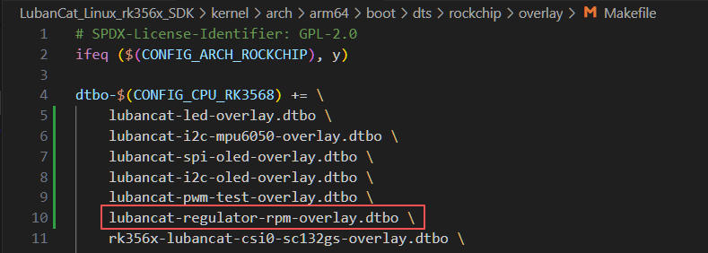
修改内核目录/arch/arm64/boot/dts/rockchip/overlays下的Makefile文件,添加我们编辑好的设备树插件,并把设备树插件文件放在和Makefile文件同级目录下,以进行设备树插件的编译。
然后在内核源码顶层目录执行以下命令编译设备树插件:
1 2 3 | #这里以rk356x系列4.19.232内核配置文件为例
make ARCH=arm64 CROSS_COMPILE=aarch64-linux-gnu- lubancat2_defconfig
make ARCH=arm64 -j4 CROSS_COMPILE=aarch64-linux-gnu- dtbs
|
提示
其余系列板卡参考 使用内核的构建脚本编译设备树插件 章节进行编译。
12.6.3.2. 加载设备树
编译出来的设备树插件位于 内核源码/arch/arm64/boot/dts/rockchip/overlay/lubancat-regulator-rpm-overlay.dtbo,
将设备树插件先传到板卡,再拷贝到板卡的 /boot/dtb/overlay/ 目录下。
1 2 3 4 | #先传输到板卡
#再拷贝到板卡的/boot/dtb/overlay/目录下
sudo cp -f lubancat-regulator-rpm-overlay.dtbo /boot/dtb/overlay/
|
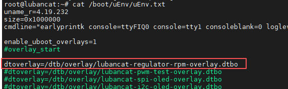
然后在 /boot/uEnv/uEnv.txt 按照格式添加我们的设备树插件,需要在#overlay_start和#overlay_end之间添加,然后重启开发板,那么系统就会加载我们编译的设备树插件。
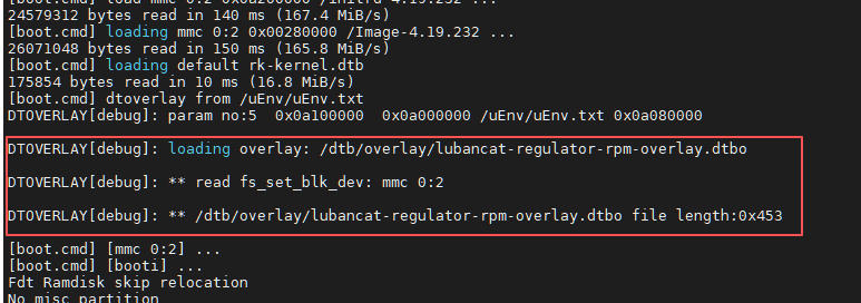
重启板卡可以在uboot启动信息中看到设备树插件加载。
12.6.3.3. 编译驱动
在实验目录下输入 make 即可编译驱动,编译得到内核模块regulator_rpm.ko。
12.6.4. 程序运行结果
如出现 Permission denied 或类似字样,请注意用户权限,大部分操作硬件外设的功能,几乎都需要root用户权限,简单的解决方案是在执行语句前加入sudo或以root用户运行程序。
12.6.4.1. 实验操作
加载设备树插件并重启板卡后会发现系统心跳灯默认 熄灭状态 ,是因为我们使用设备树插件关闭了leds节点,释放了引脚, 并使用regulator-gpio驱动将引脚注册为了调节用GPIO,开机自动使能,默认状态为高电平,所以系统心跳灯默认熄灭。
使用以下命令加载驱动和运行测试程序:
1 2 3 4 5 6 7 | #加载驱动
sudo insmod regulator_rpm.ko
#信息输出如下
[ 275.097869] regulator_rpm driver probe
[ 275.098152] regulator_rpm regulator-rpm: Linked as a consumer to regulator.19
[ 275.101985] PM suspend: regulator OFF
|
从第二条信息打印可看到Regulator 子系统绑定成功,驱动作为消费者成功获取设备树中的gpio-regulator硬件设备, regulator.19是内核为该电源设备分配的唯一编号。
从第三条信息打印可看到Runtime PM自动挂起触发,执行休眠回调函数,此时可以观察到系统心跳灯长亮,因为休眠挡位,调节用GPIO状态为低电平。
可以使用以下命令确认regulator.19的设备名称:
1 2 3 4 5 | #编号需根据实际而定,查看regulator的name
cat /sys/class/regulator/regulator.19/name
#信息打印如下,name属性和设备树配置的一致。
regulator_rpm_pwr
|
sysfs交互测试:
1 2 3 4 5 6 7 8 9 10 11 12 13 14 15 16 17 18 19 20 21 22 23 24 25 26 | #进入sysfs节点目录
cd /sys/class/regulator-rpm/regulator-test
#查看所有sysfs节点
ls -l
#信息输出如下,power_state属性目录创建成功
total 0
lrwxrwxrwx 1 root root 0 Apr 20 16:08 device -> ../../../regulator-rpm
drwxr-xr-x 2 root root 0 Apr 20 16:08 power
-rw-r--r-- 1 root root 4096 Apr 20 16:08 power_state
lrwxrwxrwx 1 root root 0 Apr 20 16:08 subsystem -> ../../../../../class/regulator-rpm
-rw-r--r-- 1 root root 4096 Apr 20 15:43 uevent
#读取电源状态
cat power_state
#信息输出如下,默认处于休眠状态
0
#触发唤醒
sudo sh -c "echo 1 > power_state"
#信息输出如下
[ 2019.654317] PM resume: regulator ON
[ 2020.656894] PM suspend: regulator OFF
|
PM resume: regulator ON:触发Runtime PM唤醒,执行resume回调,切换为3.3V档位并上电,并可以观察到系统心跳灯熄灭,即调节用GPIO状态为高电平;
PM suspend: regulator OFF:RPM自动休眠成功,1秒超时后切回0.1V,关闭电源,并可以观察到系统心跳灯常亮,即调节用GPIO状态为低电平。
12.6.5. 实验注意事项
设备树配置:regulator-gpio的gpios与states必须严格配对:states是“电压<->GPIO编码映射表”,编码顺序与gpios引脚顺序一致,写错会导致GPIO电平完全错乱。
电压宏必须与设备树states完全一致:VOLT_SUSPEND/VOLT_RESUME不可超出regulator-min/max-microvolt范围,否则内核拒绝执行。
suspend/resume时序不可颠倒:必须先切换电压->再使能/断电,否则GPIO不执行电平切换。
probe中RPM初始化顺序固定:set_active->enable->set_delay->use_autosuspend->put,顺序错误会导致RPM不工作。
pm_runtime_get/put必须严格配对:引用计数不能为负,重复put会被内核直接忽略,导致无法立即休眠。
自动挂起延迟时间合理:建议设为1000ms,太短会频繁上下电损耗硬件,太长用户感知延迟大。