7. I2C子系统–mpu6050驱动实验
I2C(Inter-Integrated Circuit)是一种同步、半双工的通信总线该总线经常在嵌入式系统中,用于连接串行EEPROM、RTC芯片、GPIO扩展器、温度传感器等 本章我们以板载MPU6050为例讲解i2c驱动程序的编写,本章主要分为五部分内容。
第一部分,i2c基本知识,回忆i2c物理总线和基本通信协议。
第二部分,linux下的i2c驱动框架。
第三部分,i2c总线驱动代码拆解。
第四部分,i2c设备驱动的核心函数。
第五部分,MPU6050驱动以及测试程序。
7.1. i2c基本知识
7.1.1. i2c物理总线
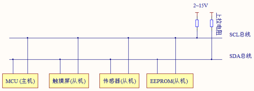
如上图所示,i2c支持一主多从,各设备地址独立,标准模式传输速率为100kbit/s,快速模式为400kbit/s。总线通过上拉电阻接到电源。 当 I2C 设备空闲时,会输出高阻态,而当所有设备都空闲,都输出高阻态时,由上拉电阻把总线拉成高电平。
I2C物理总线使用两条总线线路,SCL和SDA。
SCL: 时钟线,数据收发同步
SDA: 数据线,传输具体数据
7.1.2. i2c基本通信协议
7.1.2.1. 起始信号(S)与停止信号(P)

当SCL线为高电平时,SDA线由高到低的下降沿,为传输开始标志(S)。直到主设备发出结束信号(P), 否则总线状态一直为忙。结束标志(P)为,当SCL线为高电平时,SDA线由低到高的上升沿。
7.1.2.2. 数据格式与应答信号(ACK/NACK)
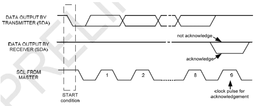
i2c的数据字节定义为8-bits长度,对每次传送的总字节数量没有限制,但对每一次传输必须伴有一个应答(ACK)信号, 其时钟由主设备提供,而真正的应答信号由从设备发出,在时钟为高时,通过拉低并保持SDA的值来实现。如果从设备忙, 它可以使 SCL保持在低电平,这会强制使主设备进入等待状态。当从设备空闲后,并且释放时钟线,原来的数据传输才会继续。
7.1.2.3. 主机与从机通信
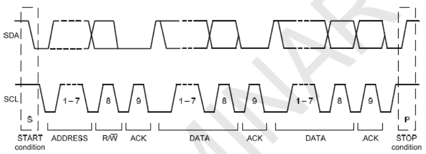
开始标志(S)发出后,主设备会传送一个7位的Slave地址,并且后面跟着一个第8位,称为Read/Write位。 R/W位表示主设备是在接受从设备的数据还是在向其写数据。然后,主设备释放SDA线,等待从设备的应答信号(ACK)。 每个字节的传输都要跟随有一个应答位。应答产生时,从设备将SDA线拉低并且在SCL为高电平时保持低。 数据传输总是以停止标志(P)结束,然后释放通信线路。 然而,主设备也可以产生重复的开始信号去操作另一台从设备, 而不发出结束标志。综上可知,所有的SDA信号变化都要在SCL时钟为低电平时进行,除了开始和结束标志
7.1.2.4. i2c对mpu6050进行数据读写
单字节写入

连续字节写入

对MPU6050进行写操作时,主设备发出开始标志(S)和写地址(地址位加一个R/W位,0为写)。 MPU6050产生应答信号。然后主设备开始传送寄存器地址(RA),接到应答后,开始传送寄存器数据, 然后仍然要有应答信号,连续写入多字节时依次类推。
单字节读出

连续字节读出

对MPU6050进行读操作时,主设备发出开始标志(S)和读地址(地址位加一个R/W位,1为读)。 等待MPU6050产生应答信号。然后发送寄存器地址,告诉MPU6050读哪一个寄存器。 紧接着,收到应答信号后,主设备再发一个开始信号,然后发送从设备读地址。 MPU6050产生应答信号并开始发送寄存器数据。通信以主设备产生的拒绝应答信号(NACK)和结束标志(P)结束。
学过单片机的用户对i2c协议并不陌生,这里只是简单的讲解,如果忘记可参考 【野火®】零死角玩转STM32 中i2c章节。
7.2. i2c驱动框架
在编写单片机裸机i2c驱动时我们需要根据i2c协议手动配置i2c控制寄存器使其能够输出起始信号、停止信号、数据信息等等。
在Linux系统中则采用了总线、设备驱动模型。我们之前讲解的平台设备也是采用了这种模型,只不过平台总线是一个虚拟的总线。
我们知道一个i2c(例如i2c1)上可以挂在多个i2c设备,例如MPU6050、i2c接口的OLED显示屏、摄像头(摄像头通过i2c接口发送控制信息)等等, 这些设备共用一个i2c,这个i2c的驱动我们称为i2c总线驱动。而对应具体的设备,例如mpu6050的驱动就是i2c设备驱动。 这样我们要使用mpu6050就需要拥有“两个驱动”一个是i2c总线驱动和mpu6050设备驱动。
i2c总线驱动由芯片厂商提供(驱动复杂,官方提供了经过测试的驱动,我们直接用),
mpu6050设备驱动可以从mpu6050芯片厂家那里获得(不确定有),也可以我们手动编写。
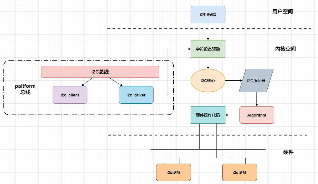
如上图所示,i2c驱动框架包括i2c总线驱动、具体某个设备的驱动。
i2c总线包括i2c设备(i2c_client)和i2c驱动(i2c_driver), 当我们向linux中注册设备或驱动的时候,按照i2c总线匹配规则进行配对,配对成功,则可以通过i2c_driver中.prob函数创建具体的设备驱动。 在现代linux中,i2c设备不再需要手动创建,而是使用设备树机制引入,设备树节点是与paltform总线相配合使用的。 所以需先对i2c总线包装一层paltform总线,当设备树节点转换为平台总线设备时,我们在进一步将其转换为i2c设备,注册到i2c总线中。
设备驱动创建成功,我们还需要实现设备的文件操作接口(file_operations),file_operations中会使用到内核中i2c核心函数(i2c系统已经实现的函数,专门开放给驱动工程师使用)。 使用这些函数会涉及到i2c适配器,也就是i2c控制器。由于ic2控制器有不同的配置,所有linux将每一个i2c控制器抽象成i2c适配器对象。 这个对象中存在一个很重要的成员变量——Algorithm,Algorithm中存在一系列函数指针,这些函数指针指向真正硬件操作代码。
7.2.1. 关键数据结构
在开始拆解i2c驱动框架的源码之前,先了解其中几个重要的对象。
struct i2c_adapter
i2c_适配器对应一个i2c控制器,是用于标识物理i2c总线以及访问它所需的访问算法的结构。
1 2 3 4 5 6 7 8 9 10 11 12 13 14 15 16 17 18 19 20 21 22 23 24 25 26 27 | /*
* i2c_adapter is the structure used to identify a physical i2c bus along
* with the access algorithms necessary to access it.
*/
struct i2c_adapter {
struct module *owner;
unsigned int class; /* classes to allow probing for */
const struct i2c_algorithm *algo; /* the algorithm to access the bus */
void *algo_data;
/* data fields that are valid for all devices */
struct rt_mutex bus_lock;
int timeout; /* in jiffies */
int retries;
struct device dev; /* the adapter device */
int nr;
char name[48];
struct completion dev_released;
struct mutex userspace_clients_lock;
struct list_head userspace_clients;
struct i2c_bus_recovery_info *bus_recovery_info;
const struct i2c_adapter_quirks *quirks;
};
|
algo: struct i2c_algorithm 结构体,访问总线的算法;
dev: struct device 结构体,控制器,表明这是一个设备。
struct i2c_algorithm
i2c_algorithm是对i2c通信方法的抽象接口,这个抽象接口使得不同芯片上的i2c外设,能使用i2c总线模型。
struct i2c_algorithm结构体用于指定访问总线(i2c)的算法, 结构体中包含了几个函数指针成员,不同的厂商根据自身硬件的特性,来自行实现自己的i2c传输功能。
更直白的说,i2c设备例如mpu6050、i2c接口的oled屏等等,就会通过这些函数接口使用i2c总线实现收、发数据的。 在i2c的总线驱动中会实现这些(部分)函数。
1 2 3 4 5 6 7 8 9 10 11 12 13 14 15 16 17 18 19 20 21 | struct i2c_algorithm {
/* If an adapter algorithm can't do I2C-level access, set master_xfer
to NULL. If an adapter algorithm can do SMBus access, set
smbus_xfer. If set to NULL, the SMBus protocol is simulated
using common I2C messages */
/* master_xfer should return the number of messages successfully
processed, or a negative value on error */
int (*master_xfer)(struct i2c_adapter *adap, struct i2c_msg *msgs,
int num);
int (*smbus_xfer) (struct i2c_adapter *adap, u16 addr,
unsigned short flags, char read_write,
u8 command, int size, union i2c_smbus_data *data);
/* To determine what the adapter supports */
u32 (*functionality) (struct i2c_adapter *);
#if IS_ENABLED(CONFIG_I2C_SLAVE)
int (*reg_slave)(struct i2c_client *client);
int (*unreg_slave)(struct i2c_client *client);
#endif
};
|
master_xfer: 作为主设备时的发送函数,应该返回成功处理的消息数,或者在出错时返回负值。
smbus_xfer: smbus是一种i2c协议的协议,如硬件上支持,可以实现这个接口。
struct i2c_client
表示i2c从设备
1 2 3 4 5 6 7 8 9 10 11 12 13 14 | struct i2c_client {
unsigned short flags; /* div., see below */
unsigned short addr; /* chip address - NOTE: 7bit */
char name[I2C_NAME_SIZE];
struct i2c_adapter *adapter; /* the adapter we sit on */
struct device dev; /* the device structure */
int init_irq; /* irq set at initialization */
int irq; /* irq issued by device */
struct list_head detected;
#if IS_ENABLED(CONFIG_I2C_SLAVE)
i2c_slave_cb_t slave_cb; /* callback for slave mode */
#endif
};
|
flags: :I2C_CLIENT_TEN表示设备使用10位芯片地址,I2C客户端PEC表示它使用SMBus数据包错误检查
addr: addr在连接到父适配器的I2C总线上使用的地址。
name: 表示设备的类型,通常是芯片名。
adapter: struct i2c_adapter 结构体,管理托管这个I2C设备的总线段。
dev: Driver model设备节点。
init_irq: 作为从设备时的发送函数。
irq: 表示该设备生成的中断号。
detected: struct list_head i2c的成员_驱动程序.客户端列表或i2c核心的用户空间设备列表。
slave_cb: 使用适配器的I2C从模式时回调。适配器调用它来将从属事件传递给从属驱动程序。i2c_客户端识别连接到i2c总线的单个设备(即芯片)。暴露在Linux下的行为是由管理设备的驱动程序定义的。
struct i2c_driver
i2c设备驱动程序
1 2 3 4 5 6 7 8 9 10 11 12 13 14 15 16 | struct i2c_driver {
unsigned int class;
int (*probe)(struct i2c_client *, const struct i2c_device_id *);
int (*remove)(struct i2c_client *);
struct device_driver driver;
const struct i2c_device_id *id_table;
int (*detect)(struct i2c_client *, struct i2c_board_info *);
const unsigned short *address_list;
struct list_head clients;
...
};
|
probe: i2c设备和i2c驱动匹配后,回调该函数指针。
id_table: struct i2c_device_id 要匹配的从设备信息。
address_list: 设备地址
clients: 设备链表
detect: 设备探测函数
7.3. i2c总线驱动
i2c总线驱动由芯片厂商提供,如果我们使用rk官方提供的Linux内核,i2c总线驱动已经保存在内核中,并且默认情况下已经编译进内核。
下面结合源码简单介绍i2c总线的运行机制。
1、注册I2C总线
2、将I2C驱动添加到I2C总线的驱动链表中
3、遍历I2C总线上的设备链表,根据i2c_device_match函数进行匹配,如果匹配调用i2c_device_probe函数
4、i2c_device_probe函数会调用I2C驱动的probe函数
i2c总线定义
1 2 3 4 5 6 7 | struct bus_type i2c_bus_type = {
.name = "i2c",
.match = i2c_device_match,
.probe = i2c_device_probe,
.remove = i2c_device_remove,
.shutdown = i2c_device_shutdown,
};
|
i2c总线维护着两个链表(I2C驱动、I2C设备),管理I2C设备和I2C驱动的匹配和删除等
i2c总线注册
linux启动之后,默认执行i2c_init。
1 2 3 4 5 6 7 8 9 10 11 12 13 14 15 16 17 18 19 20 21 22 | static int __init i2c_init(void)
{
int retval;
...
retval = bus_register(&i2c_bus_type);
if (retval)
return retval;
is_registered = true;
...
retval = i2c_add_driver(&dummy_driver);
if (retval)
goto class_err;
if (IS_ENABLED(CONFIG_OF_DYNAMIC))
WARN_ON(of_reconfig_notifier_register(&i2c_of_notifier));
if (IS_ENABLED(CONFIG_ACPI))
WARN_ON(acpi_reconfig_notifier_register(&i2c_acpi_notifier));
return 0;
...
}
|
第5行:bus_register注册总线i2c_bus_type,总线定义如上所示。
第11行:i2c_add_driver注册设备dummy_driver。
i2c设备和i2c驱动匹配规则
1 2 3 4 5 6 7 8 9 10 11 12 13 14 15 16 17 18 19 20 21 | static int i2c_device_match(struct device *dev, struct device_driver *drv)
{
struct i2c_client *client = i2c_verify_client(dev);
struct i2c_driver *driver;
/* Attempt an OF style match */
if (i2c_of_match_device(drv->of_match_table, client))
return 1;
/* Then ACPI style match */
if (acpi_driver_match_device(dev, drv))
return 1;
driver = to_i2c_driver(drv);
/* Finally an I2C match */
if (i2c_match_id(driver->id_table, client))
return 1;
return 0;
}
|
of_driver_match_device: 设备树匹配方式,比较 I2C 设备节点的 compatible 属性和 of_device_id 中的 compatible 属性
acpi_driver_match_device: ACPI 匹配方式
i2c_match_id: i2c总线传统匹配方式,比较 I2C设备名字和 i2c驱动的id_table->name 字段是否相等
在i2c总线驱动代码源文件中,我们只简单介绍重要的几个点,如果感兴趣可自行阅读完整的i2c驱动源码。 通常情况下,看驱动程序首先要找到驱动的入口和出口函数,驱动入口和出口位于驱动的末尾,如下所示(rk3568):
1 2 3 4 5 6 7 8 9 10 | static struct platform_driver rk3x_i2c_driver = {
.probe = rk3x_i2c_probe,
.remove = rk3x_i2c_remove,
.driver = {
.name = "rk3x-i2c",
.of_match_table = rk3x_i2c_match,
.pm = &rk3x_i2c_pm_ops,
},
};
module_platform_driver(rk3x_i2c_driver);
|
驱动注册函数module_platform_driver(定义在内核源码/include/linux/platform_device.h),该宏详细请参考前面动态设备树章节, 我们可以从中得到i2c驱动是一个平台驱动,并且我们知道平台驱动结构体是“rk3x_i2c_driver”,平台驱动结构体如下所示。
1 2 3 4 5 6 7 8 9 10 11 12 13 14 15 16 17 18 19 20 21 22 23 24 25 26 27 28 29 30 31 32 33 34 35 36 37 38 39 40 41 42 | static const struct of_device_id rk3x_i2c_match[] = {
{
.compatible = "rockchip,rv1108-i2c",
.data = &rv1108_soc_data
},
{
.compatible = "rockchip,rv1126-i2c",
.data = &rv1126_soc_data
},
{
.compatible = "rockchip,rk3066-i2c",
.data = &rk3066_soc_data
},
{
.compatible = "rockchip,rk3188-i2c",
.data = &rk3188_soc_data
},
{
.compatible = "rockchip,rk3228-i2c",
.data = &rk3228_soc_data
},
{
.compatible = "rockchip,rk3288-i2c",
.data = &rk3288_soc_data
},
{
.compatible = "rockchip,rk3399-i2c",
.data = &rk3399_soc_data
},
{},
};
MODULE_DEVICE_TABLE(of, rk3x_i2c_match);
static struct platform_driver rk3x_i2c_driver = {
.probe = rk3x_i2c_probe,
.remove = rk3x_i2c_remove,
.driver = {
.name = "rk3x-i2c",
.of_match_table = rk3x_i2c_match,
.pm = &rk3x_i2c_pm_ops,
},
};
|
第1-5行:是i2c驱动的匹配表,用于和设备树节点匹配,
第8-16行:是初始化的平台设备结构体,从这个结构体我们可以找到.prob函数,.prob函数的作用我们都很清楚,通常情况下该函数实现设备的基本初始化。
以下是.porbe函数的内容。
1 2 3 4 5 6 7 8 9 10 11 12 13 14 15 16 17 18 19 20 21 22 23 24 25 26 27 28 29 30 31 32 33 34 35 36 37 38 39 40 41 42 43 44 45 46 47 48 49 50 51 52 53 54 55 56 57 58 59 60 61 62 63 64 65 66 67 68 69 70 71 72 73 74 75 76 77 78 79 80 81 82 83 84 85 86 87 88 89 90 91 92 93 94 95 96 97 98 99 100 101 102 103 104 105 106 107 108 109 110 111 112 113 114 115 116 117 118 119 120 121 122 123 124 125 126 127 128 129 130 131 132 133 134 135 136 137 138 139 140 141 142 143 144 145 146 147 148 149 150 151 152 153 154 155 156 157 158 159 | static int rk3x_i2c_probe(struct platform_device *pdev)
{
struct device_node *np = pdev->dev.of_node;
const struct of_device_id *match;
struct rk3x_i2c *i2c;
struct resource *mem;
int ret = 0;
u32 value;
int irq;
unsigned long clk_rate;
i2c = devm_kzalloc(&pdev->dev, sizeof(struct rk3x_i2c), GFP_KERNEL); //分配内存空间rk3x_i2c结构体
if (!i2c)
return -ENOMEM;
match = of_match_node(rk3x_i2c_match, np); //找到匹配的设备节点的of_device_id
i2c->soc_data = match->data; //通过of_device_id,获取.data 成员,即.data = &rk3399_soc_data
/* use common interface to get I2C timing properties */
i2c_parse_fw_timings(&pdev->dev, &i2c->t, true);
strlcpy(i2c->adap.name, "rk3x-i2c", sizeof(i2c->adap.name));
i2c->adap.owner = THIS_MODULE;
i2c->adap.algo = &rk3x_i2c_algorithm;
i2c->adap.retries = 3;
i2c->adap.dev.of_node = np;
i2c->adap.algo_data = i2c;
i2c->adap.dev.parent = &pdev->dev;
i2c->dev = &pdev->dev;
spin_lock_init(&i2c->lock);
init_waitqueue_head(&i2c->wait);
i2c->i2c_restart_nb.notifier_call = rk3x_i2c_restart_notify;
i2c->i2c_restart_nb.priority = 128;
ret = register_pre_restart_handler(&i2c->i2c_restart_nb);
if (ret) {
dev_err(&pdev->dev, "failed to setup i2c restart handler.\n");
return ret;
}
mem = platform_get_resource(pdev, IORESOURCE_MEM, 0);
i2c->regs = devm_ioremap_resource(&pdev->dev, mem);
if (IS_ERR(i2c->regs))
return PTR_ERR(i2c->regs);
/*
* Switch to new interface if the SoC also offers the old one.
* The control bit is located in the GRF register space.
*/
if (i2c->soc_data->grf_offset >= 0) {
struct regmap *grf;
grf = syscon_regmap_lookup_by_phandle(np, "rockchip,grf");
if (!IS_ERR(grf)) {
int bus_nr;
/* Try to set the I2C adapter number from dt */
bus_nr = of_alias_get_id(np, "i2c");
if (bus_nr < 0) {
dev_err(&pdev->dev, "rk3x-i2c needs i2cX alias");
return -EINVAL;
}
if (i2c->soc_data == &rv1108_soc_data && bus_nr == 2)
/* rv1108 i2c2 set grf offset-0x408, bit-10 */
value = BIT(26) | BIT(10);
else if (i2c->soc_data == &rv1126_soc_data &&
bus_nr == 2)
/* rv1126 i2c2 set pmugrf offset-0x118, bit-4 */
value = BIT(20) | BIT(4);
else
/* rk3xxx 27+i: write mask, 11+i: value */
value = BIT(27 + bus_nr) | BIT(11 + bus_nr);
ret = regmap_write(grf, i2c->soc_data->grf_offset,
value);
if (ret != 0) {
dev_err(i2c->dev, "Could not write to GRF: %d\n",
ret);
return ret;
}
}
}
/* IRQ setup */
irq = platform_get_irq(pdev, 0);
if (irq < 0) {
dev_err(&pdev->dev, "cannot find rk3x IRQ\n");
return irq;
}
ret = devm_request_irq(&pdev->dev, irq, rk3x_i2c_irq,
0, dev_name(&pdev->dev), i2c);
if (ret < 0) {
dev_err(&pdev->dev, "cannot request IRQ\n");
return ret;
}
platform_set_drvdata(pdev, i2c);
if (i2c->soc_data->calc_timings == rk3x_i2c_v0_calc_timings) {
/* Only one clock to use for bus clock and peripheral clock */
i2c->clk = devm_clk_get(&pdev->dev, NULL);
i2c->pclk = i2c->clk;
} else {
i2c->clk = devm_clk_get(&pdev->dev, "i2c");
i2c->pclk = devm_clk_get(&pdev->dev, "pclk");
}
if (IS_ERR(i2c->clk)) {
ret = PTR_ERR(i2c->clk);
if (ret != -EPROBE_DEFER)
dev_err(&pdev->dev, "Can't get bus clk: %d\n", ret);
return ret;
}
if (IS_ERR(i2c->pclk)) {
ret = PTR_ERR(i2c->pclk);
if (ret != -EPROBE_DEFER)
dev_err(&pdev->dev, "Can't get periph clk: %d\n", ret);
return ret;
}
ret = clk_prepare(i2c->clk);
if (ret < 0) {
dev_err(&pdev->dev, "Can't prepare bus clk: %d\n", ret);
return ret;
}
ret = clk_prepare(i2c->pclk);
if (ret < 0) {
dev_err(&pdev->dev, "Can't prepare periph clock: %d\n", ret);
goto err_clk;
}
i2c->clk_rate_nb.notifier_call = rk3x_i2c_clk_notifier_cb;
ret = clk_notifier_register(i2c->clk, &i2c->clk_rate_nb);
if (ret != 0) {
dev_err(&pdev->dev, "Unable to register clock notifier\n");
goto err_pclk;
}
clk_rate = clk_get_rate(i2c->clk);
rk3x_i2c_adapt_div(i2c, clk_rate);
ret = i2c_add_adapter(&i2c->adap);
if (ret < 0)
goto err_clk_notifier;
return 0;
err_clk_notifier:
clk_notifier_unregister(i2c->clk, &i2c->clk_rate_nb);
err_pclk:
clk_unprepare(i2c->pclk);
err_clk:
clk_unprepare(i2c->clk);
return ret;
}
|
第12-14行:为rk3x_i2c结构体申请空间,后面会详述这个结构体。
第43-44行:获取reg属性,这里使用的是内核提供的“platform_get_resource”它实现的功能和我们使用of函数获取reg属性相同。这里的代码获取得到了i2c的基地址,并且使用“devm_ioremap_resource”将其转化为虚拟地址。
第87-99行:获取中断号,在i2c的设备树节点中定义了中断,这里获取得到的中断号申请中断时会用到,获取函数使用的是内核提供的函数irq_of_parse_and_map。
第122-144行:获取时钟配置并配置。
剩余的都是pm功耗管理,adapter的配置了,比较简单, 最终使用i2c_add_adapter函数将平台驱动注册到bus中。
下面我们来看看rk3x_i2c结构体,它是切实用于产商芯片和linux平台关联的桥梁。
1 2 3 4 5 6 7 8 9 10 11 12 13 14 15 16 17 18 19 20 21 22 23 24 25 26 27 28 29 30 31 32 33 34 | struct rk3x_i2c {
struct i2c_adapter adap;
struct device *dev;
const struct rk3x_i2c_soc_data *soc_data;
/* Hardware resources */
void __iomem *regs;
struct clk *clk;
struct clk *pclk;
struct notifier_block clk_rate_nb;
/* Settings */
struct i2c_timings t;
/* Synchronization & notification */
spinlock_t lock;
wait_queue_head_t wait;
bool busy;
/* Current message */
struct i2c_msg *msg;
u8 addr;
unsigned int mode;
bool is_last_msg;
/* I2C state machine */
enum rk3x_i2c_state state;
unsigned int processed;
int error;
unsigned int suspended:1;
struct notifier_block i2c_restart_nb;
bool system_restarting;
};
|
rk3x_i2c结构体成员较多,描述了厂商的i2c控制器信息以及即将注册到总线中的adapter适配器, 通过这个结构体,可以关联linux下的i2c总线模型和产商芯片驱动功能。
adap: 即将注册到总线中的adapter适配器
irq: 保存i2c的中断号
clk: clk结构体保存时钟相关信息
busy: 事件等待的条件
在前面的probe函数函数中,初始化rk3x_i2c结构体中的adap成员。
我们重点看60行的:“i2c->adap.algo = &rk3x_i2c_algorithm”, 它就是用于初始化“访问i2c总线的传输算法”。“st_i2c_algo”定义如下。
1 2 3 4 | static const struct i2c_algorithm rk3x_i2c_algorithm = {
.master_xfer = rk3x_i2c_xfer,
.functionality = rk3x_i2c_func,
};
|
st_i2c_algo结构体内指定了两个函数,它们就是外部访问i2c总线的接口:
函数rk3x_i2c_func只是用于返回I2C总线提供的功能。
函数rk3x_i2c_xfer真正实现访问i2c外设,进行数据传输。
rk3x_i2c_xfer函数定义如下:
1 2 3 4 5 6 7 8 9 10 11 12 13 14 15 16 17 18 19 20 21 22 23 24 25 26 27 28 29 30 31 32 33 34 35 36 37 38 39 40 41 42 43 44 45 46 47 48 49 50 51 52 53 54 55 56 57 58 59 60 61 62 63 64 65 66 67 68 69 70 71 72 73 74 75 | static int rk3x_i2c_xfer(struct i2c_adapter *adap,
struct i2c_msg *msgs, int num)
{
struct rk3x_i2c *i2c = (struct rk3x_i2c *)adap->algo_data;
unsigned long timeout, flags;
u32 val;
int ret = 0;
int i;
if (i2c->suspended)
return -EACCES;
spin_lock_irqsave(&i2c->lock, flags);
clk_enable(i2c->clk);
clk_enable(i2c->pclk);
i2c->is_last_msg = false;
/*
* Process msgs. We can handle more than one message at once (see
* rk3x_i2c_setup()).
*/
for (i = 0; i < num; i += ret) {
ret = rk3x_i2c_setup(i2c, msgs + i, num - i);
if (ret < 0) {
dev_err(i2c->dev, "rk3x_i2c_setup() failed\n");
break;
}
if (i + ret >= num)
i2c->is_last_msg = true;
rk3x_i2c_start(i2c);
spin_unlock_irqrestore(&i2c->lock, flags);
timeout = wait_event_timeout(i2c->wait, !i2c->busy,
msecs_to_jiffies(WAIT_TIMEOUT));
spin_lock_irqsave(&i2c->lock, flags);
if (timeout == 0) {
dev_err(i2c->dev, "timeout, ipd: 0x%02x, state: %d\n",
i2c_readl(i2c, REG_IPD), i2c->state);
/* Force a STOP condition without interrupt */
rk3x_i2c_disable_irq(i2c);
val = i2c_readl(i2c, REG_CON) & REG_CON_TUNING_MASK;
val |= REG_CON_EN | REG_CON_STOP;
i2c_writel(i2c, val, REG_CON);
i2c->state = STATE_IDLE;
ret = -ETIMEDOUT;
break;
}
if (i2c->error) {
ret = i2c->error;
break;
}
}
rk3x_i2c_disable_irq(i2c);
rk3x_i2c_disable(i2c);
clk_disable(i2c->pclk);
clk_disable(i2c->clk);
spin_unlock_irqrestore(&i2c->lock, flags);
return ret < 0 ? ret : num;
}
|
在编写设备驱动如mpu6050的驱动时,我们会使用“i2c_transfer”函数执行数据的传输,i2c_transfer函数最终就是调用rk3x_i2c_xfer函数实现具体的收发工作。 届时我们会详细介绍i2c_transfer函数的用法。
在rk3x_i2c_xfer中,实际的收发又是通过rk3x_i2c_setup来完成,函数实现如下:
static int rk3x_i2c_setup(struct rk3x_i2c *i2c, struct i2c_msg *msgs, int num)
{
    u32 addr = (msgs[0].addr & 0x7f) << 1;
    int ret = 0;

    /*
    * The I2C adapter can issue a small (len < 4) write packet before
    * reading. This speeds up SMBus-style register reads.
    * The MRXADDR/MRXRADDR hold the slave address and the slave register
    * address in this case.
    */

    if (num >= 2 && msgs[0].len < 4 &&
        !(msgs[0].flags & I2C_M_RD) && (msgs[1].flags & I2C_M_RD)) {
        u32 reg_addr = 0;
        int i;

        dev_dbg(i2c->dev, "Combined write/read from addr 0x%x\n",
            addr >> 1);

        /* Fill MRXRADDR with the register address(es) */
        for (i = 0; i < msgs[0].len; ++i) {
            reg_addr |= msgs[0].buf[i] << (i * 8);
            reg_addr |= REG_MRXADDR_VALID(i);
        }

        /* msgs[0] is handled by hw. */
        i2c->msg = &msgs[1];

        i2c->mode = REG_CON_MOD_REGISTER_TX;

        i2c_writel(i2c, addr | REG_MRXADDR_VALID(0), REG_MRXADDR);
        i2c_writel(i2c, reg_addr, REG_MRXRADDR);

        ret = 2;
    } else {
        /*
        * We'll have to do it the boring way and process the msgs
        * one-by-one.
        */

        if (msgs[0].flags & I2C_M_RD) {
            addr |= 1; /* set read bit */

            /*
            * We have to transmit the slave addr first. Use
            * MOD_REGISTER_TX for that purpose.
            */
            i2c->mode = REG_CON_MOD_REGISTER_TX;
            i2c_writel(i2c, addr | REG_MRXADDR_VALID(0),
                REG_MRXADDR);
            i2c_writel(i2c, 0, REG_MRXRADDR);
        } else {
            i2c->mode = REG_CON_MOD_TX;
        }

        i2c->msg = &msgs[0];

        ret = 1;
    }

    i2c->addr = msgs[0].addr;
    i2c->busy = true;
    i2c->processed = 0;
    i2c->error = 0;

    rk3x_i2c_clean_ipd(i2c);

    return ret;
}
这里就不带大家展开了,操作内容都是比较针对底层外设寄存器的,简单解释参考代码中的注释。
至此我们的i2c平台驱动就给大家分析完了,probe函数完成了i2c的基本初始化并将其添加到了系统中。 驱动中也实现i2c对外接口函数。 我们在初始化i2c_adapter结构体时已经初始化了访问总线算法结构体i2c_algorithm,在前面也介绍过了。
那么总结整个probe函数,主要完成了两个工作。第一,初始化i2c硬件,第二,初始化一个可以访问i2c外设的i2c_adapter结构体,并将其添加到系统中。
7.4. i2c设备驱动核心函数
i2c_add_adapter()
向linux系统注册一个i2c适配器
1 2 3 4 | //linux系统自动设置i2c适配器编号(adapter->nr)
int i2c_add_adapter(struct i2c_adapter *adapter)
//手动设置i2c适配器编号(adapter->nr)
int i2c_add_numbered_adapter(struct i2c_adapter *adapter)
|
参数:
adapter: i2c物理控制器对应的适配器
返回值:
成功: 0
失败: 负数
i2c_add_driver()宏
1 | #define i2c_add_driver(driver)
|
这个宏函数的本质是调用了i2c_register_driver()函数,函数如下。
i2c_register_driver()函数
1 | int i2c_register_driver(struct module *owner, struct i2c_driver *driver)
|
参数:
owner: 一般为 THIS_MODULE
driver: 要注册的 i2c_driver.
返回值:
成功: 0
失败: 负数
i2c_transfer()函数
i2c_transfer()函数最终就是调用我们前面讲到的rk3x_i2c_xfer()函数来实现数据传输。
1 | int i2c_transfer(struct i2c_adapter *adap, struct i2c_msg *msgs, int num)
|
参数:
adap : struct i2c_adapter 结构体,收发消息所使用的i2c适配器,i2c_client 会保存其对应的 i2c_adapter
msgs: struct i2c_msg 结构体,i2c要发送的一个或多个消息
num : 消息数量,也就是msgs的数量
返回值:
成功: 发送的msgs的数量
失败: 负数
i2c_msg结构体
1 2 3 4 5 6 7 | struct i2c_msg {
__u16 addr; /* slave address */
__u16 flags;
...
__u16 len; /* msg length */
__u8 *buf; /* pointer to msg data */
};
|
addr: iic设备地址
flags: 消息传输方向和特性。I2C_M_RD:表示读取消息;0:表示发送消息。
len: 消息数据的长度
buf: 字符数组存放消息,作为消息的缓冲区
i2c_master_send()函数
1 2 3 4 5 | static inline int i2c_master_send(const struct i2c_client *client,
const char *buf, int count)
{
return i2c_transfer_buffer_flags(client, (char *)buf, count, 0);
};
|
i2c_master_recv()函数
1 2 3 4 5 | static inline int i2c_master_recv(const struct i2c_client *client,
char *buf, int count)
{
return i2c_transfer_buffer_flags(client, buf, count, I2C_M_RD);
};
|
i2c_transfer_buffer_flags()函数
1 2 3 4 5 6 7 8 9 10 11 12 13 14 15 16 17 18 19 | int i2c_transfer_buffer_flags(const struct i2c_client *client, char *buf,
int count, u16 flags)
{
int ret;
struct i2c_msg msg = {
.addr = client->addr,
.flags = flags | (client->flags & I2C_M_TEN),
.len = count,
.buf = buf,
};
ret = i2c_transfer(client->adapter, &msg, 1);
/*
* If everything went ok (i.e. 1 msg transferred), return #bytes
* transferred, else error code.
*/
return (ret == 1) ? count : ret;
}
|
下面以mpu6050为例讲解如何编写i2c设备驱动。
7.5. mpu6050驱动实验
7.5.1. 硬件介绍
本节实验使用lubancat2板卡,以及 《野火MPU6050模块》 。
MPU6050是一款运动处理传感器,它集成了3轴MEMS陀螺仪,3轴MEMS加速度计。
mpu6050和lubancat2的引脚连接对应表:
MPU6050引脚(模块丝印) |
说明 |
lubancat2板卡引脚 |
|---|---|---|
SCL |
SCL引脚 |
I2C3_SCL |
SDA |
SDA引脚 |
I2C3_SDA |
XDA |
没有使用 |
|
XCL |
没有使用 |
|
AD0 |
接地 |
GND |
int |
悬空或者接地 |
|
GND |
GND |
GND |
VCC |
电源 |
3.3V |
提示
lubancat2板卡引出引脚,请看“LubanCat-RK系列板卡快速使用手册”的40pin引脚对照图。
MPU6050是通过i2c连接到开发板的,其中传感器上的SDA和SCL连到开发板i2c3, 开发板要控制MPU6050需要先复用这两个引脚为i2c控制器引脚。
查看MPU芯片手册我们可以知道,MPU6050的slave地址为b110100X,七位字长,最低有效位X由AD0管脚上的逻辑电平决定。 从原理图上可以看到,AD0接地,则地址为b1101000,也就是0x68,另外,中断引脚“int”没有使用。
7.5.1.1. 设备树
lubancat2板卡,使用i2c3 m0和mpu6050通信,下面是ic3控制器的设备树代码:
1 2 3 4 5 6 7 8 9 10 11 12 13 | i2c3: i2c@fe5c0000 {
compatible = "rockchip,rk3399-i2c";
reg = <0x0 0xfe5c0000 0x0 0x1000>;
clocks = <&cru CLK_I2C3>, <&cru PCLK_I2C3>;
clock-names = "i2c", "pclk";
interrupts = <GIC_SPI 49 IRQ_TYPE_LEVEL_HIGH>;
pinctrl-names = "default";
pinctrl-0 = <&i2c3m0_xfer>; //默认是GPIO0_A1和GPIO0_A0复用为I2C3引脚
#address-cells = <1>;
#size-cells = <0>;
status = "disabled";
};
|
1 2 3 4 5 6 7 8 9 10 11 12 13 14 15 16 17 | i2c3 {
i2c3m0_xfer: i2c3m0-xfer {
rockchip,pins =
/* i2c3_sclm0 */
<1 RK_PA1 1 &pcfg_pull_none_smt>,
/* i2c3_sdam0 */
<1 RK_PA0 1 &pcfg_pull_none_smt>;
};
i2c3m1_xfer: i2c3m1-xfer {
rockchip,pins =
/* i2c3_sclm1 */
<3 RK_PB5 4 &pcfg_pull_none_smt>,
/* i2c3_sdam1 */
<3 RK_PB6 4 &pcfg_pull_none_smt>;
};
};
|
1 2 3 4 5 6 7 8 9 10 11 12 13 14 15 16 17 18 19 20 21 22 23 24 25 26 27 | /*
* Copyright (C) 2022 - All Rights Reserved by
* EmbedFire LubanCat
*/
/dts-v1/;
/plugin/;
#include <dt-bindings/gpio/gpio.h>
#include <dt-bindings/pinctrl/rockchip.h>
#include <dt-bindings/clock/rk3568-cru.h>
#include <dt-bindings/interrupt-controller/irq.h>
&i2c3 {
status = "okay";
pinctrl-names = "default";
pinctrl-0 = <&i2c3m0_xfer>; //使用GPIO0_A1和GPIO0_A0复用为I2C3引脚
#address-cells = <1>;
#size-cells = <0>;
mpu6050@68 {
compatible = "fire,i2c_mpu6050";
//compatible = "invensense,mpu6050"
reg = <0x68>;
status = "okay";
};
};
|
第15行: 将i2c3节点打开
第17行: 使用i2c3m1作为i2c3的引脚
第21行: 添加MPU6050子节点
第22-23行: 设置MPU6050子节点属性为”fire,i2c_mpu6050”,和驱动保持一致即可。我们注释掉了”invensense,mpu6050”, 此属性可以使用到内核自带的mpu6050驱动,自带的mpu6050驱动是使用ii0子系统来实现的,感兴趣可自行研究。
如果要修改其他为引脚,根据实际使用的引脚将第15行和17行修改为实际使用的i2c和相应发复用引脚即可。
7.5.2. 实验代码讲解
7.5.2.2. mpu6050驱动实现
由于rockchip官方已经写好了i2c的总线驱动,mpu6050这个设备驱动就变得很简单,下面结合代码介绍mpu6050设别驱动实现。
和平台设备驱动类似,mpu6050驱动程序结构如下:
1 2 3 4 5 6 7 8 9 10 11 12 13 14 15 16 17 18 19 20 21 22 23 24 25 26 27 28 29 30 31 32 33 34 35 36 37 38 39 40 41 42 43 44 45 46 47 48 49 50 51 52 53 54 55 56 57 58 59 60 61 62 63 64 65 66 67 68 69 70 71 72 73 74 75 | static int i2c_write_mpu6050(struct i2c_client *mpu6050_client, u8 address, u8 data)
{
return 0;
}
static int i2c_read_mpu6050(struct i2c_client *mpu6050_client, u8 address, void *data, u32 length)
{
return 0;
}
static int mpu6050_init(void)
{
return 0;
}
/*字符设备操作函数集,open函数实现*/
static int mpu6050_open(struct inode *inode, struct file *filp)
{
return 0;
}
/*字符设备操作函数集,.read函数实现*/
static ssize_t mpu6050_read(struct file *filp, char __user *buf, size_t cnt, loff_t *off)
{
return 0;
}
/*字符设备操作函数集,.release函数实现*/
static int mpu6050_release(struct inode *inode, struct file *filp)
{
return 0;
}
/*字符设备操作函数集*/
static struct file_operations mpu6050_chr_dev_fops =
{
.owner = THIS_MODULE,
.open = mpu6050_open,
.read = mpu6050_read,
.release = mpu6050_release,
};
/*i2c总线设备函数集*/
static int mpu6050_probe(struct i2c_client *client, const struct i2c_device_id *id)
{
return 0;
}
static int mpu6050_remove(struct i2c_client *client)
{
/*删除设备*/
return 0;
}
/*定义i2c总线设备结构体*/
struct i2c_driver mpu6050_driver = {
.probe = mpu6050_probe,
.remove = mpu6050_remove,
.id_table = gtp_device_id,
};
/*
* 驱动初始化函数
*/
static int __init mpu6050_driver_init(void)
{
return 0;
}
/*
* 驱动注销函数
*/
static void __exit mpu6050_driver_exit(void)
{
}
module_init(mpu6050_driver_init);
module_exit(mpu6050_driver_exit);
MODULE_LICENSE("GPL");
|
驱动程序可分为如下四部分内容(从下往上看):
第49-73行: 定义i2c总线设备结构体并实现i2c总线设备的注册和注销函数,在这里就是程驱动程序的入口和出口函数。
第38-47行: 实现i2c总线设备结构体中定义的操作函数,主要是.prob匹配函数,在.prob函数中添加、注册一个字符设备,这个字符设备用于实现mpu6050的具体功能。
第14-36行: 定义并实现字符设备操作函数集。在应用程序中的open、read操作传到内核后就是执行这些函数,所以他们要真正实现对mpu6050的初始化以及读取转换结果。
第1-12行: 具体的读、写mpu6050的函数,它们被第三部分的函数调用,用户自行定义。
下面我们将按照这四部分内容介绍mpu6050设备驱动程序实现。
7.5.2.2.1. 驱动入口和出口函数实现
驱动入口和出口函数仅仅用于注册、注销i2c设备驱动,代码如下:
1 2 3 4 5 6 7 8 9 10 11 12 13 14 15 16 17 18 19 20 21 22 23 24 25 26 27 28 29 30 31 32 33 34 35 36 37 38 39 40 41 42 43 44 45 46 | /*定义ID 匹配表*/
static const struct i2c_device_id gtp_device_id[] = {
{"fire,i2c_mpu6050", 0},
{}};
/*定义设备树匹配表*/
static const struct of_device_id mpu6050_of_match_table[] = {
{.compatible = "fire,i2c_mpu6050"},
{/* sentinel */}};
/*定义i2c设备结构体*/
struct i2c_driver mpu6050_driver = {
.probe = mpu6050_probe,
.remove = mpu6050_remove,
.id_table = gtp_device_id,
.driver = {
.name = "fire,i2c_mpu6050",
.owner = THIS_MODULE,
.of_match_table = mpu6050_of_match_table,
},
};
/*
*驱动初始化函数
*/
static int __init mpu6050_driver_init(void)
{
int ret;
pr_info("mpu6050_driver_init\n");
ret = i2c_add_driver(&mpu6050_driver);
return ret;
}
/*
*驱动注销函数
*/
static void __exit mpu6050_driver_exit(void)
{
pr_info("mpu6050_driver_exit\n");
i2c_del_driver(&mpu6050_driver);
}
module_init(mpu6050_driver_init);
module_exit(mpu6050_driver_exit);
MODULE_LICENSE("GPL");
|
第1-9行: 定义设备树匹配表。
第13-14行: .probe和.remove,它们是i2c设备的操作函数,.prob函数在匹配成功后会执行,设备注销之前.remove函数会执行,稍后我们会实现这两个函数。
第12-21行: 定义的i2c设备驱动结构体mpu6050_driver,和我们之前学习的平台设备驱动类似,一个“结构体”代表了一个设备。结构体内主要成员介绍如下, “.id_table”和“.of_match_table”,它们用于和匹配设备树节点,具体实现如代码如第二行、第七行。
第26-41行: 就是我们常说的驱动入口和出口函数。在入口函数内我们调用“i2c_add_driver”函数添加一个i2c设备驱动。在出口函数内调用“i2c_del_driver”函数删除一个i2c设备驱动。它们的参数都只有一个i2c设备驱动结构体。
7.5.2.2.2. .prob函数和.remove函数实现
通常情况下.prob用于实现一些初始化工作,.remove用于实现退出之前的清理工作。 mpu6050需要初始化的内容很少,我们放到了字符设备的.open函数中实现.prob函数只需要添加、注册一个字符设备即可。 程序源码如下所示:
1 2 3 4 5 6 7 8 9 10 11 12 13 14 15 16 17 18 19 20 21 22 23 24 | static int mpu6050_probe(struct i2c_client *client, const struct i2c_device_id *id)
{
int ret = -1; //保存错误状态码
printk(KERN_EMERG "\t match successed \n");
//采用动态分配的方式,获取设备编号,次设备号为0
ret = alloc_chrdev_region(&mpu6050_devno, 0, DEV_CNT, DEV_NAME);
if (ret < 0)
{
printk("fail to alloc mpu6050_devno\n");
goto alloc_err;
}
...
}
static int mpu6050_remove(struct i2c_client *client)
{
/*删除设备*/
device_destroy(class_mpu6050, mpu6050_devno); //清除设备
class_destroy(class_mpu6050); //清除类
cdev_del(&mpu6050_chr_dev); //清除设备号
unregister_chrdev_region(mpu6050_devno, DEV_CNT); //取消注册字符设备
return 0;
}
|
.prob函数仅仅注册了一个字符设备,注册字符设备已经在之前的驱动程序中多次使用,这里不再赘述。
.remove函数工作是注销字符设备。
7.5.2.2.3. 实现字符设备操作函数集
在.prob函数中添加了一个字符设备,mpu6050的初始化以及转换结果的读取都在这个字符设备的操作函数中实现, 其中最主要是.open 和.read函数。下面是这两个函数的实现。
.open函数实现(我们在.open函数中配置mpu6050),具体代码如下:
1 2 3 4 5 6 7 8 9 10 11 12 13 14 15 16 17 18 19 20 21 22 23 24 25 26 27 28 29 30 31 32 33 34 35 36 37 38 39 40 41 42 43 44 45 46 47 48 49 50 51 52 53 54 55 56 57 58 59 60 61 62 | /*字符设备操作函数集,open函数实现*/
static int mpu6050_open(struct inode *inode, struct file *filp)
{
// printk("\n mpu6050_open \n");
/*向 mpu6050 发送配置数据,让mpu6050处于正常工作状态*/
mpu6050_init();
return 0;
}
/*初始化i2c
*返回值,成功,返回0。失败,返回 -1
*/
static int mpu6050_init(void)
{
int error = 0;
/*配置mpu6050*/
error += i2c_write_mpu6050(mpu6050_client, PWR_MGMT_1, 0X00);
error += i2c_write_mpu6050(mpu6050_client, SMPLRT_DIV, 0X07);
error += i2c_write_mpu6050(mpu6050_client, CONFIG, 0X06);
error += i2c_write_mpu6050(mpu6050_client, ACCEL_CONFIG, 0X01);
if (error < 0)
{
/*初始化错误*/
printk(KERN_DEBUG "\n mpu6050_init error \n");
return -1;
}
return 0;
}
/*通过i2c 向mpu6050写入数据
*mpu6050_client:mpu6050的i2c_client结构体。
*address, 数据要写入的地址,
*data, 要写入的数据
*返回值,错误,-1。成功,0
*/
static int i2c_write_mpu6050(struct i2c_client *mpu6050_client, u8 address, u8 data)
{
int error = 0;
u8 write_data[2];
struct i2c_msg send_msg; //要发送的数据结构体
/*设置要发送的数据*/
write_data[0] = address;
write_data[1] = data;
/*发送 iic要写入的地址 reg*/
send_msg.addr = mpu6050_client->addr; //mpu6050在 iic 总线上的地址
send_msg.flags = 0; //标记为发送数据
send_msg.buf = write_data; //写入的首地址
send_msg.len = 2; //reg长度
/*执行发送*/
error = i2c_transfer(mpu6050_client->adapter, &send_msg, 1);
if (error != 1)
{
printk(KERN_DEBUG "\n i2c_transfer error \n");
return -1;
}
return 0;
}
|
第2行: 在.open函数中仅仅调用了我们自己编写的mpu6050_init函数。
第13-29行: 调用i2c_write_mpu6050函数向mpu6050发送控制参数,控制参数可参考芯片手册,我们重点讲解函数i2c_write_mpu6050实现。
第33行: 参数mpu6050_client是i2c_client类型的结构体,填入mpu6050设备对应的i2c_client结构体即可。
第34行: 参数address,用于设置要写入的地址这个地址是要写入mpu6050的内部地址。
第35行: 参数data, 指定要写入的数据。
第42行: 定义struct i2c_msg结构体,用来装要发送数据。
第45-46行: 写入数据时要先发送写入的地址然后发送要写入的数据,这里用长度为二的数组保存地址和数据
第49-52: i2c_msg结构体填入总线上的地址,标记发送数据,首地址,以及reg长度。
第55行: i2c_write_mpu6050函数,该函数是对i2c_transfer函数的封装,而i2c_transfer是系统提供的i2c设备驱动发送函数,根据之前讲解这个函数最终会调用i2c总线驱动里的函数,最终由i2c总线驱动执行收、发工作。我们这里要做的就是按照规定的格式编写要发送的数据。
mpu6050_read函数源码如下所示。
1 2 3 4 5 6 7 8 9 10 11 12 13 14 15 16 17 18 19 20 21 22 23 24 25 26 27 28 29 30 31 32 33 34 35 36 37 38 39 40 41 42 43 44 45 46 47 48 49 | /*字符设备操作函数集,.read函数实现*/
static ssize_t mpu6050_read(struct file *filp, char __user *buf, size_t cnt, loff_t *off)
{
char data_H;
char data_L;
int error;
short mpu6050_result[6]; //保存mpu6050转换得到的原始数据
i2c_read_mpu6050(mpu6050_client, ACCEL_XOUT_H, &data_H, 1);
i2c_read_mpu6050(mpu6050_client, ACCEL_XOUT_L, &data_L, 1);
mpu6050_result[0] = data_H << 8;
mpu6050_result[0] += data_L;
i2c_read_mpu6050(mpu6050_client, ACCEL_YOUT_H, &data_H, 1);
i2c_read_mpu6050(mpu6050_client, ACCEL_YOUT_L, &data_L, 1);
mpu6050_result[1] = data_H << 8;
mpu6050_result[1] += data_L;
i2c_read_mpu6050(mpu6050_client, ACCEL_ZOUT_H, &data_H, 1);
i2c_read_mpu6050(mpu6050_client, ACCEL_ZOUT_L, &data_L, 1);
mpu6050_result[2] = data_H << 8;
mpu6050_result[2] += data_L;
i2c_read_mpu6050(mpu6050_client, GYRO_XOUT_H, &data_H, 1);
i2c_read_mpu6050(mpu6050_client, GYRO_XOUT_L, &data_L, 1);
mpu6050_result[3] = data_H << 8;
mpu6050_result[3] += data_L;
i2c_read_mpu6050(mpu6050_client, GYRO_YOUT_H, &data_H, 1);
i2c_read_mpu6050(mpu6050_client, GYRO_YOUT_L, &data_L, 1);
mpu6050_result[4] = data_H << 8;
mpu6050_result[4] += data_L;
i2c_read_mpu6050(mpu6050_client, GYRO_ZOUT_H, &data_H, 1);
i2c_read_mpu6050(mpu6050_client, GYRO_ZOUT_L, &data_L, 1);
mpu6050_result[5] = data_H << 8;
mpu6050_result[5] += data_L;
/*将读取得到的数据拷贝到用户空间*/
error = copy_to_user(buf, mpu6050_result, cnt);
if(error != 0)
{
printk("copy_to_user error!");
return -1;
}
return 0;
}
|
.read函数很简单,大致分为如下两部分,重点是i2c_read_mpu6050函数的实现。
第10-38行: 调用i2c_read_mpu6050函数读取mpu6050转换结果。
第41行: 调用copy_to_user函数将转换得到的数据拷贝到用户空间。
1 2 3 4 5 6 7 8 9 10 11 12 13 14 15 16 17 18 19 20 21 22 23 24 25 26 27 | static int i2c_read_mpu6050(struct i2c_client *mpu6050_client, u8 address, void *data, u32 length)
{
int error = 0;
u8 address_data = address;
struct i2c_msg mpu6050_msg[2];
/*设置读取位置i2c_msg*/
mpu6050_msg[0].addr = mpu6050_client->addr; //mpu6050在 iic 总线上的地址
mpu6050_msg[0].flags = 0; //标记为发送数据
mpu6050_msg[0].buf = &address_data; //写入的首地址
mpu6050_msg[0].len = 1; //写入长度
/*读取i2c_msg*/
mpu6050_msg[1].addr = mpu6050_client->addr; //mpu6050在 iic 总线上的地址
mpu6050_msg[1].flags = I2C_M_RD; //标记为读取数据
mpu6050_msg[1].buf = data; //读取得到的数据保存位置
mpu6050_msg[1].len = length; //读取长度
error = i2c_transfer(mpu6050_client->adapter, mpu6050_msg, 2);
if (error != 2)
{
printk(KERN_DEBUG "\n i2c_read_mpu6050 error \n");
return -1;
}
return 0;
}
|
它与我们之前讲解的i2c_write_mpu6050函数很相似,结合源码介绍如下:
第1行: 参数mpu6050_client是i2c_client类型的结构体,填入mpu6050设备对应的i2c_client结构体即可。参数address,用于设置要读取的地址这个地址是要读取的mpu6050的内部地址。参数data,保存读取得到的数据。参数length,指定去取长度,单位字节。
第3-5行: 定义的一些变量,其中i2c_msg结构体,读取工作与写入不同,读取时需要先写入要读取的地址然后再执行读取。
第8-17行: 初始化i2c_msg结构体。这里初始化了两个,第一个是写入要读取的地址,第二个执行读取,特别注意的是第一个i2c_msg结构体的flags设置为0(或者I2C_M_RD | I2C_M_REV_DIR_ADDR),第二个i2c_msg结构体的flags设置为1(或者I2C_M_RD)。
第19行: 和i2c_write_mpu6050()函数相同,调用i2c_transfer函数,最终由i2c总线驱动执行收、发工作。
7.5.2.3. mpu6050测试应用程序实现
这里编写一个简单地测试应用程序测试驱动是否正常,很简单,只需要打开、读取、打印即可。测试代码如下所示。
1 2 3 4 5 6 7 8 9 10 11 12 13 14 15 16 17 18 19 20 21 22 23 24 25 26 27 28 29 30 31 32 33 34 35 36 37 38 39 | #include <stdio.h>
#include <unistd.h>
#include <fcntl.h>
#include <string.h>
#include <stdlib.h>
int main(int argc, char *argv[])
{
short resive_data[6];
printf("led_tiny test\n");
/*打开文件*/
int fd = open("/dev/I2C1_mpu6050", O_RDWR);
if(fd < 0)
{
printf("open file : %s failed !\n", argv[0]);
return -1;
}
/*读取数据*/
int error = read(fd,resive_data,12);
if(error < 0)
{
printf("write file error! \n");
close(fd);
/*判断是否关闭成功*/
}
printf("AX=%d, AY=%d, AZ=%d ",(int)resive_data[0],(int)resive_data[1],(int)resive_data[2]);
printf("GX=%d, GY=%d, GZ=%d \n \n",(int)resive_data[3],(int)resive_data[4],(int)resive_data[5]);
/*关闭文件*/
error = close(fd);
if(error < 0)
{
printf("close file error! \n");
}
return 0;
}
|
第8行: 保存收到的 mpu6050转换结果数据,依次为 AX(x轴角度), AY, AZ 。GX(x轴加速度), GY ,GZ
第12-17行: 打开MPU6050设备文件。
第20-29行: 读取传感器是并打印
测试应用程序很简单,我们不过多介绍,只说明一点,在驱动的.read函数中我们每次读取了6050的AX, AY, AZ ,GX, GY ,GZ共六个short类型数据,在应用程序中每次读取也要读这么多。
7.5.3. 实验准备
7.5.3.1. 通过内核工具编译设备树插件
设备树插件与设备树一样都是使用DTC工具编译,只不过设备树编译为.dtb。而设备树插件需要编译为.dtbo。 我们可以使用DTC编译命令编译生成.dtbo,但是这样比较繁琐、容易出错。
我们可以修改内核目录/arch/arm/boot/dts/overlays下的Makefile文件, 添加我们编辑好的设备树插件。并把设备树插件文件放在和Makefile文件同级目录下。 以进行设备树插件的编译,详细看下 环境搭建章节。
在内核的根目录下执行如下命令即可:
make ARCH=arm64 CROSS_COMPILE=aarch64-linux-gnu- lubancat2_defconfig  //以lubancat2为例

make ARCH=arm64 -j4 CROSS_COMPILE=aarch64-linux-gnu- dtbs
生成的.dtbo位于内核根目录下的“arch/arm64/boot/dts/rockchip/overlays”目录下。
编译成功后生成的设备树插件文件(lubancat-mpu6050-overlay.dtbo)位于源码目录下的 内核源码/arch/arm64/boot/dts/rockchip/overlays/
7.5.3.2. 编译驱动程序和应用程序
将 linux_driver/ 拷贝到内核源码同级目录,进入 I2c_MPU6050/ 目录,执行make命令,生成i2c_mpu6050.ko和6050_test_app
7.5.4. 程序运行结果
7.5.4.1. 加载设备树插件
通过SCP、NFS或者sftp将编译好的设备树插件拷贝到开发板上。把设备树插件 lubancat-mpu6050-overlay.dtbo 复制到 /boot/dtb/overlay/ 目录下。
该实验以lubancat2为例,打开/boot/ueEnv目录下的uEnvLubanCat2.txt文件,修改如下内容。
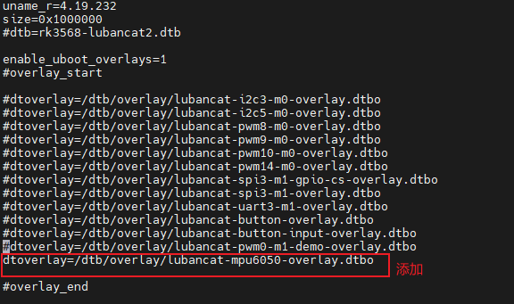
重启开发板,设备树插件加载成功后会有:

7.5.4.2. 测试效果
将先前编译好的i2c_mpu6050.ko驱动及测试app上传至开发板中。
加载i2c_mpu6050.ko,改变mpu6050的姿态,运行6050_test_app即可看到如下效果。
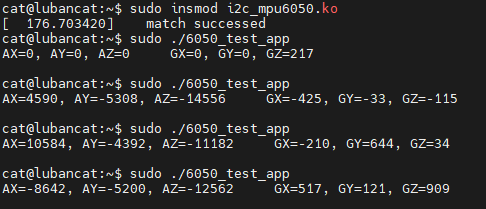
注意:这里采集的是原始数据,所以波动较大是正常的。
