8. 设备树插件修改方法指导
在Linux系统中,绝大多数硬件设备都有非常成熟的驱动框架,驱动工程师使用这些框架添加与板子相关的硬件支持, 建立硬件与Linux内核的联系。修改设备树则是建立与驱动之间的联系。
8.1. LED子系统设备树插件编写
下面以LED子系统设备为例,想要根据LED子系统编写相对应的设备树,可参考的资料有以下
imx-fire-led-overlay.dts 野火提供的设备树插件源文件,这部分是最简单最快速的参考资料,只要依葫芦画瓢即可写出自己的设备树插件。
Documentation/devicetree/bindings/leds/leds-gpio.txt 简单介绍了led子系统的相关节点,提供了led子系统设备树编写的参考例子。
Documentation/devicetree/bindings/leds/common.txt 提供了led子系统设备通用的设备树节点说明。
下面将以leds-gpio.txt和common.txt文档为指导,以imx-fire-led-overlay.dts为参考, 整理编写基于LED子系统设备树插件思路。
8.1.1. 设备树插件编写框架
在前一篇基础知识中,已经介绍设备树插件的编写框架,直接拿过来使用即可。
1 2 3 4 5 6 7 8 9 10 11 | /dts-v1/;
/plugin/;
/{
fragment@0 {
target-path = "/";
__overlay__ {
/*在此添加要插入的节点*/
};
};
};
|
8.1.2. 配置GPIO引脚功能
查看野火imx6ull底板原理图,可知LED_R对应引脚GPIO_4,LED_G对应引脚CSI_HSYNC,LED_B对应引脚CSI_VSYNC
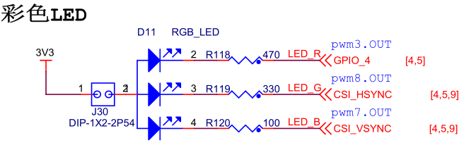
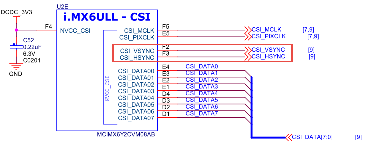
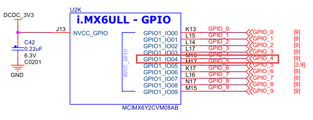
查看imx6ull核心板原理图,进一步确定引脚编号 可知GPIO_4为引脚GPIO1_IO04,CSI_HSYNC为CSI_HSYNC,CSI_VSYNC为引脚CSI_VSYNC。
注解
CSI_HSYNC和CSI_VSYNC都是引脚名,若想确定是芯片上的哪个物理引脚需要查询数据手册。
一款强大的MCU/MPU引脚都能够配置为各种不同的引脚功能,因此我们需要在设备树插件中将上面引脚设置为IO引脚模式。 为节省篇幅,此处仅配置LED_B引脚功能。
1 2 3 4 5 6 7 8 9 10 11 12 13 14 15 16 17 18 19 20 21 22 23 24 25 26 27 28 29 30 | /dts-v1/;
/plugin/;
#include "imx6ul-pinfunc.h"
/{
fragment@0 {
target-path = "/";
__overlay__ {
normal_led{
led_blue{
pinctrl-names = "default";
pinctrl-0 = <&pinctrl_blue>;
};
};
};
};
fragment@1 {
target = <&iomuxc>;
__overlay__ {
pinctrl_blue:bluegrp{
fsl,pins = < MX6UL_PAD_CSI_VSYNC__GPIO4_IO19 0x1b0b0>;
};
};
};
};
|
“imx6ul-pinfunc.h”头文件中包含了各种引脚复用关系,如 “MX6UL_PAD_CSI_VSYNC__GPIO4_IO19”宏。
向“/{……}”根节点中追加了添加normal_led节点,其中包括led_blue{……}子节点, 并将使用pinctrl_blue节点的IO引脚。
向iomuxc节点中追加pinctrl_blue:bluegrp{……}节点,将CSI_VSYNC引脚设置为IO模式。
提示
其中0x1b0b0设置值,直接参考imx-fire-led-overlay.dts中的文件。用户也可 参考 Documentation/devicetree/bindings/pinctrl/fsl,imx6ul-pinctrl.txt 文档中说明配置。
8.1.3. 添加led子系统相关节点信息
想要添加与LED子系统相关的节点信息,查看 Documentation/devicetree/bindings/leds/ 目录下的 leds-gpio.txt 与 common.txt 文档必不可少。添加代码如下
1 2 3 4 5 6 7 8 9 10 11 12 13 14 15 16 17 18 19 20 21 22 23 24 25 26 27 28 29 30 31 32 33 34 35 36 37 | /dts-v1/;
/plugin/;
#include "dt-bindings/gpio/gpio.h"
#include "imx6ul-pinfunc.h"
/{
fragment@0 {
target-path = "/";
__overlay__ {
normal_led{
compatible = "gpio-leds";
led_blue{
pinctrl-names = "default";
pinctrl-0 = <&pinctrl_blue>;
label = "led_blue";
default-state = "off" ;
linux,default-trigger = "none";
gpios = <&gpio4 19 GPIO_ACTIVE_LOW>;
};
};
};
};
fragment@1 {
target = <&iomuxc>;
__overlay__ {
pinctrl_blue:bluegrp{
fsl,pins = < MX6UL_PAD_CSI_VSYNC__GPIO4_IO19 0x1b0b0>;
};
};
};
};
|
dt-bindings/gpio/gpio.h 的头文件包含了 GPIO_ACTIVE_LOW 相关的宏。
compatible、label、default-state、linux,default-trigger、gpios 在 leds-gpio.txt 与 common.txt 文件中均有介绍。部分文档如下所示
1 2 3 4 5 6 7 8 9 10 11 12 13 14 15 16 | Required properties:
- compatible : should be "gpio-leds".
Each LED is represented as a sub-node of the gpio-leds device. Each
node's name represents the name of the corresponding LED.
LED sub-node properties:
- gpios : Should specify the LED's GPIO, see "gpios property" in
Documentation/devicetree/bindings/gpio/gpio.txt. Active low LEDs should be
indicated using flags in the GPIO specifier.
- label : (optional)
see Documentation/devicetree/bindings/leds/common.txt
- linux,default-trigger : (optional)
see Documentation/devicetree/bindings/leds/common.txt
- default-state: (optional) The initial state of the LED.
see Documentation/devicetree/bindings/leds/common.txt
|
提示
Documentation/devicetree 目录下的文档是编写设备树插件必看文档。
以上即是参考官方文档编写设备树插件的的基本步骤。
8.2. 基于野火提供的设备树插件修改
有了章节前面的基础再根据自己的需求修改设备树插件那就容易多了。 野火提供了大量的设备树插件可供参考,用户只需要根据相关相对应的设备树插件修改即可。
为了减少文章篇幅,以下只列出imx-fire-led-overlay.dts源码中对RGB中的红灯设备树部分。
1 2 3 4 5 6 7 8 9 10 11 12 13 14 15 16 17 18 19 20 21 22 23 24 25 26 27 28 29 30 31 | /dts-v1/;
/plugin/;
#include "imx6ul-pinfunc.h"
#include "dt-bindings/gpio/gpio.h"
/ {
fragment@0 {
target-path = "/";
__overlay__ {
normal_led{
compatible = "gpio-leds";
red {
pinctrl-names = "default";
pinctrl-0 = <&pinctrl_red>;
label = "red";
gpios = <&gpio1 4 GPIO_ACTIVE_LOW>;
default-state = "off";
linux,default-trigger = "none";
};
};
};
};
fragment@1 {
target= <&iomuxc>;
__overlay__{
pinctrl_red:redgrp{
fsl,pins = < MX6UL_PAD_GPIO1_IO04__GPIO1_IO04 0x1b0b0 >;
};
};
};
};
|
如果用户想要添加一个LED子系统相关的设备,核心基本上只需要修改以上两条语句, 节点名与标签可根据自己设备情况灵活修改。 同理其他设备树插件的修改也是类似。
8.3. 参考资料
对于LED设备,Linux提供了LED子系统驱动框架, 在Linux内核源码中的“Documentation/leds/leds-class.txt”有相关的描述, 《控制LED灯设备(LED子系统使用方法)》