4. 创建任务
现在让我们体验下怎么使用STM32CubeIDE创建RTOS线程,并以不同的速率闪烁两个不同的LED灯。 作为本书第一个实验,将完整展示整个工程创建的过程,在以后的章节中重点放在RTOS功能的讲解上。
4.2. 创建STM32CubeIDE工程
4.2.1. 选择创建STM32MP157工程
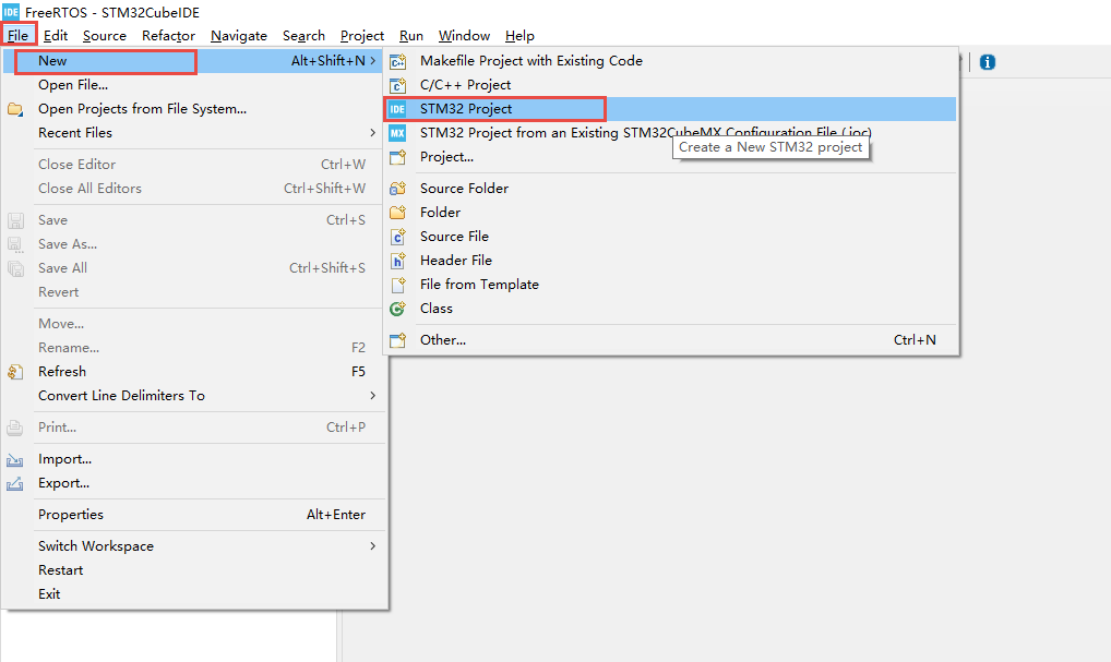
打开STM32CubeIDE之后,选择File->New->STM32 Project
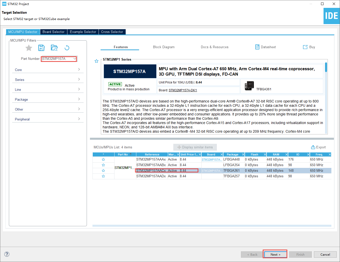
搜索STM32MP157A,选择STM32MP157AACx系列,然后选择Next
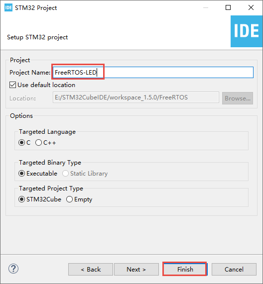
根据喜好选择输入的工程名,选择Finish。
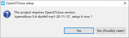
弹出以下窗口选择No。
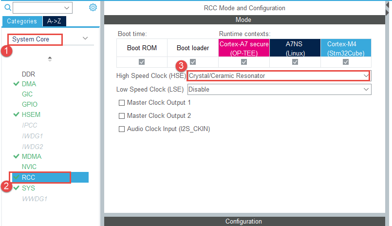
4.2.2. 时钟及通用设置配置
选择RCC外设,设置选择外部高速时钟晶振。
设置时钟树,选择使用外部高速时钟经过PPL3倍频得到的时钟作为MCU的时钟源,并设置时钟源频率为209Mhz。 若无特殊说明,在本书其他工程中时钟源均是如此配置。
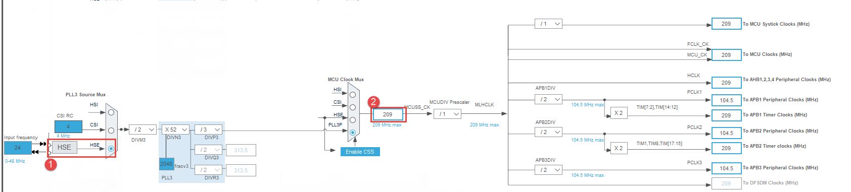
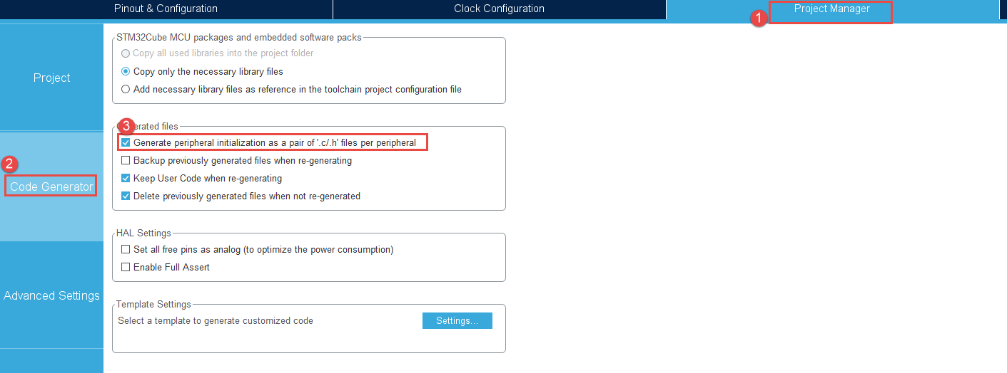
选择为每个外设生成独立的.c/.h文件。
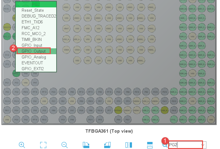
4.2.3. 引脚功能配置
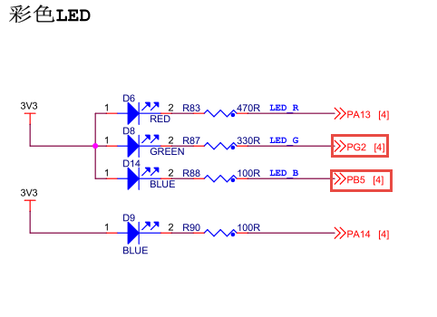
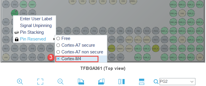
在本次实验中我们将控制两个LED,将其所在的引脚PG2、PB5设置为输出模式,并分配给Cortex-M4内核。
设置 PG2 引脚为输出模式。
选择分配给Cortex-M4内核
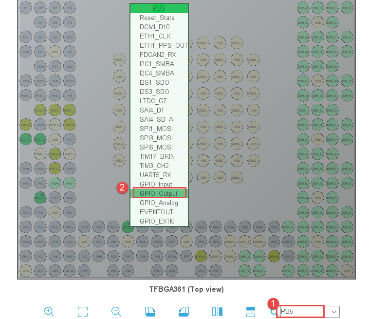
设置 PB5 引脚为输出模式。
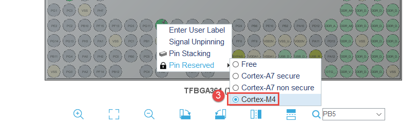
选择分配给Cortex-M4内核
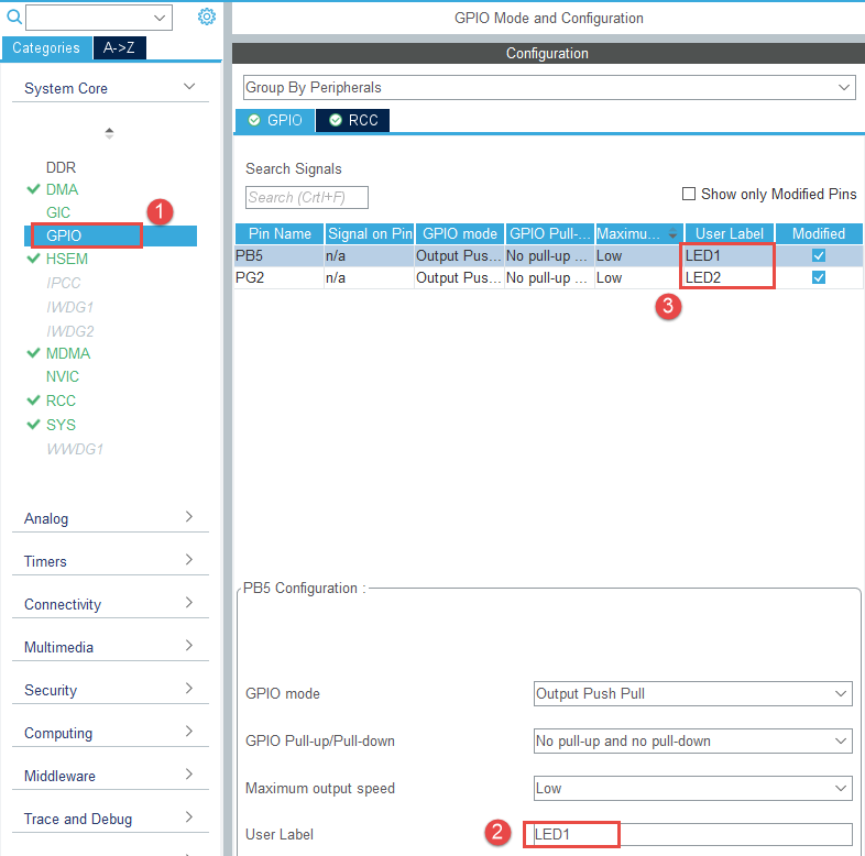
设置引脚标签
4.2.4. 配置FreeRTOS
选择Middleware->FREERTOS,函数接口选择CMSIS_V2,CMSIS_V1官方已不在维护。
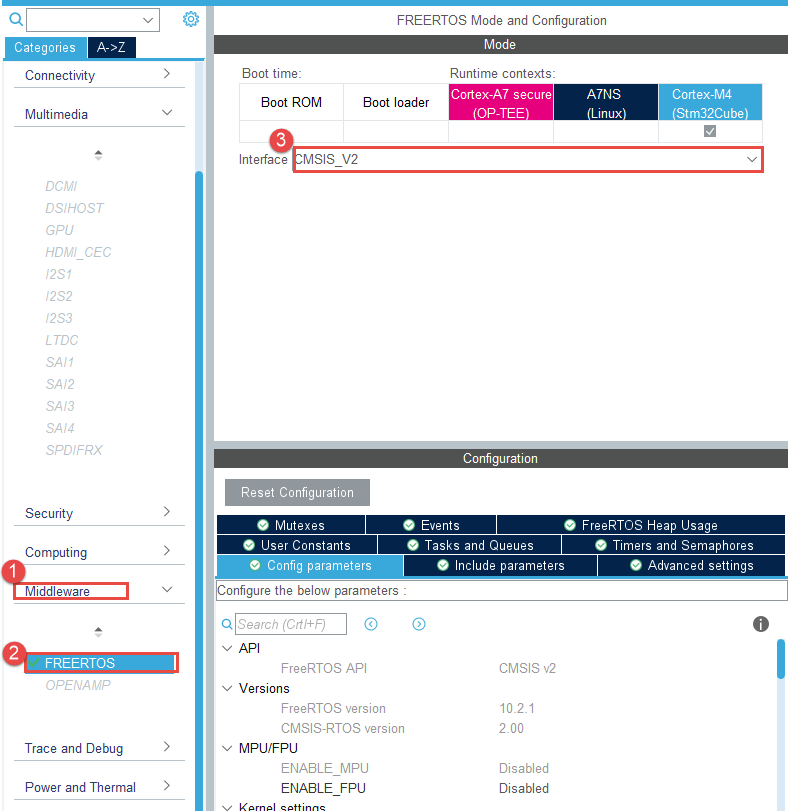
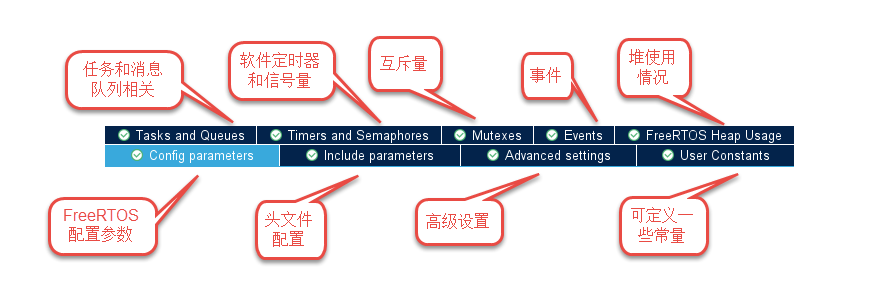
这里先简单介绍下FreeRTOS的配置界面,首先是以下几个可切换的窗口,当我们需要配置 某些功能时,就需要进入不同的窗口进行配置。如在本章实验中需要使用两个线程, 就得在Tasks and Queues窗口中添加新的线程。
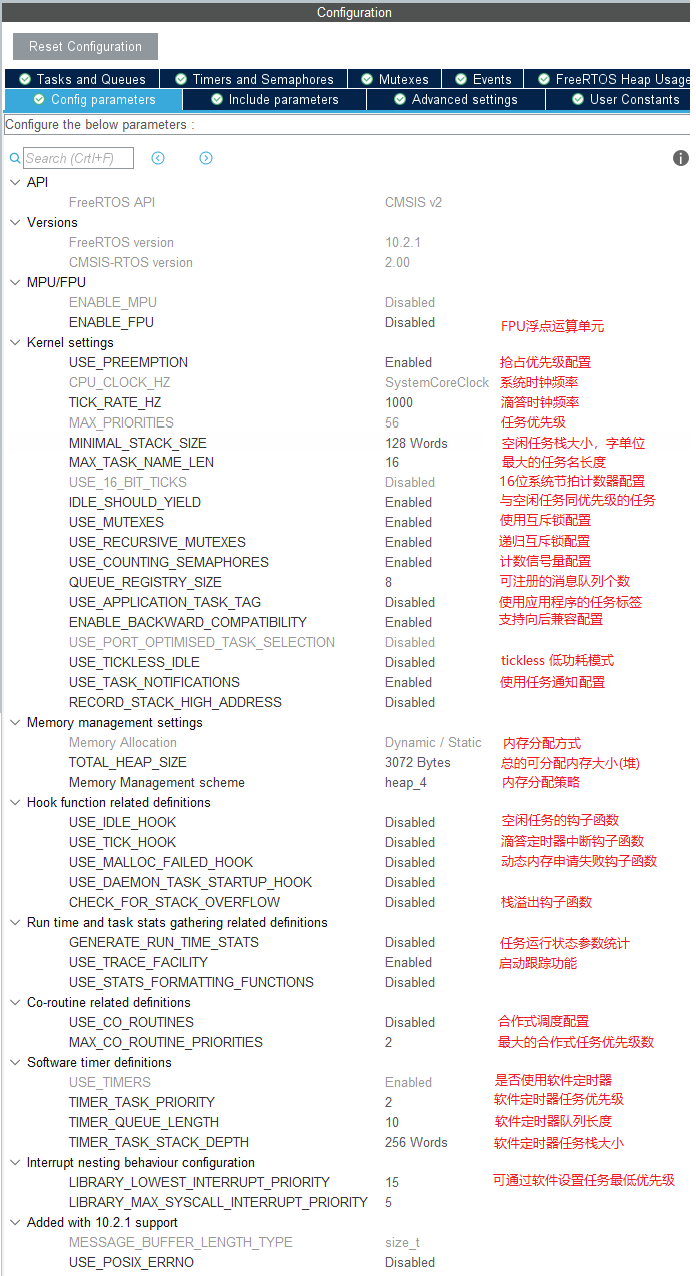
在Config parameters窗口中有着各式各样的配置参数,我们也将大部分配置参数的作用用中文在旁边 进行了简单的注释,FreeRTOS很多组件都是可裁剪的,用户可根据实际需求添加或剔除使用不到的功能, 初学者暂无需理会此处的配置信息,保持默认配置即可。
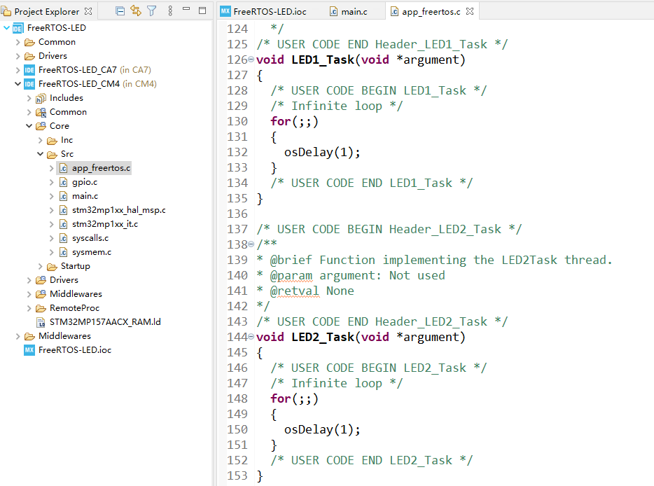
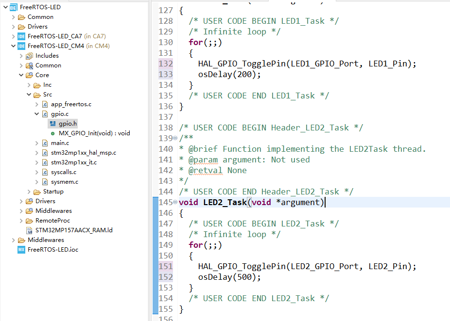
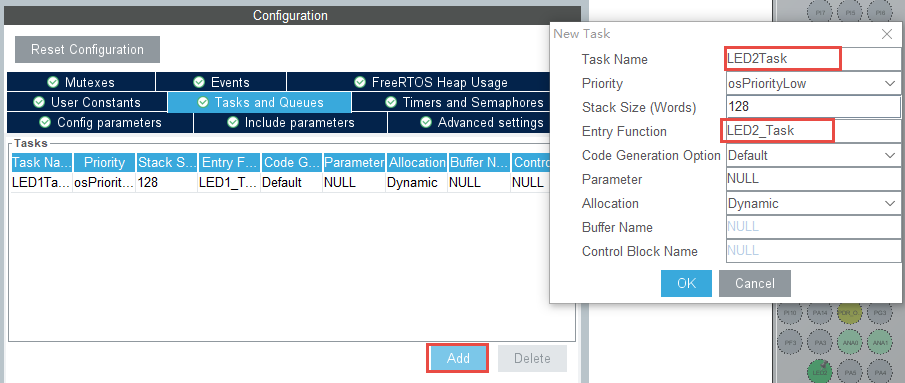
在FreeRTOS的配置窗口下选择Tasks and Queues,STM32CubeIDE默认创建一个线程, 双击可进行线程配置。可根据自己的命名喜好重新命名,此处我们将其修改为”LED1Task”, 函数名为”LED1_Task”。其他保持默认即可。
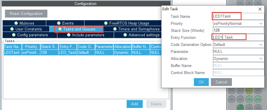
配置选项介绍如下
Task Name :用于设置线程名。
Priority :用于设置线程优先级。
Stack Size(Words) :用于设置线程栈大小。
Entry Function :用于设置线程函数名。
Code Generation Option :代码的生成方式选项,可选择以弱定义形式生成。
Parameter :线程函数参数
Allocation :选择使用动态内存分配的还是静态内存的方式创建线程。
Buffer Name :当使用静态内存创建线程,使用的栈地址名。
Control Block Name:当使用静态内存创建线程,创建的线程控制块变量名。
新建另外一个线程,名为”LED2Task”。
到此关于STM32CubeIDE配置生成FreeRTOS已经配置完毕。
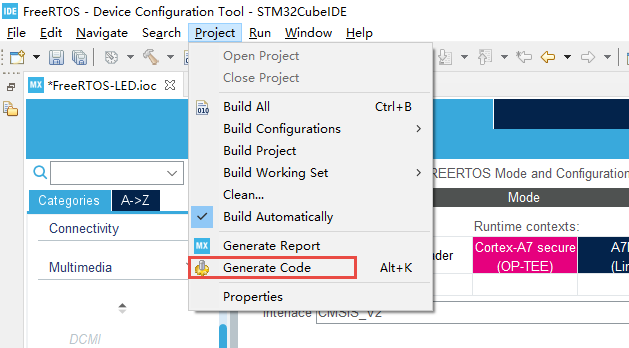
4.2.5. 生成代码
选择Project-> Generate Code 生成项目代码。
此处会弹出一个警告,提示我们Systick定时器已被HAL库占用,在STM32MP157 Cortex-M4内核上我们更换不了 其他的定时器,选择Yes继续生成代码即可。
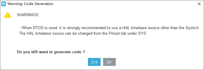
到此使用STM32CubeIDE生成FreeRTOS的工程完毕。